 Object
Type
The object type: curve, surface, polysurface, block name, etc. displays.
Name
Object names are stored in the Rhino 3DM file and exported to file formats that accept object names.
See: Naming conventions in Rhino
Layer
To change the object's layers, select a layer from the list. Layers can be created, and their properties can be changed in the Layer dialog box.
Right-click on the layer entry to show the context menu.
Copy Layer Path to Clipboard
Copies the full layer to the clipboard. Parent and child layers are separated by double colons. For example:
Layer 01::Layer 02::Layer 03
View in Layers Panel
Selects the object's layer in the Layers panel.
Display Color
The color of the object can either inherit the color of its layer or be set as an object property.
 By Layer
Uses the display color of the object's layer.
 By Parent
When the object is in a block, it displays with the display color of its parent (the block instance).
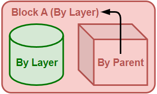
This option is only useful for objects in blocks. Think of a block instance as a container that contains objects (block members). A block instance is the parent of its block members. A block instance has its own properties. If By Parent is selected in the properties of a block member, the properties will be controlled by the block instance.
Simple block example:
-
In this example, Block A contains a cylinder and a box. The Display Color of the box is By Parent and is controlled by its parent (Block A). The box will display Block A's layer color because the display color of Block A is By Layer. The cylinder will always display its own layer color and will not be changed by Block A.
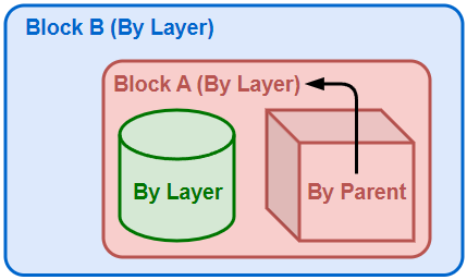
Nested block example:
-
Now Block A is nested in Block B. The box still displays Block A's layer color because By Parent only works with the direct parent.
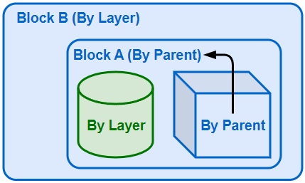
-
If the Display Color of Block A is changed to By Parent, the display color of the box will be indirectly controlled by its grandparent (Block B).
 By Material
The object displays with the base color of the material assigned to it.
- Assigning per-face materials to an Extrusion converts the Extrusion to a polysurface.
 Custom
Pick a color from the Select Color dialog box.
Unset Color (For Sub-faces only)
Unset Color indicates the selected sub-face does not have a per-face color assigned.
When a per-face color exists, selecting Unset Color clears the per-face color.
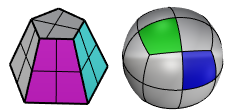
To change polysurface/SubD sub-face color
-
Ctrl(CMD)+Shift+Click sub-faces before selecting a color.
- Use the RemovePerFaceColors command to remove per-face display colors from an object.
- To remove per-face display color from a specific face, use Unset Color.
- Assigning per-face colors to an Extrusion converts the Extrusion to a polysurface.
Display Mode
By View
Sets the object to display with the viewport display mode.
<Display mode>
Select a display mode for the object to override the display mode of the current viewport. How the object displays in other viewports is not affected.
Multiple Viewports
Shows a dialog that lists all the viewports in the model. It allows you to set how the object displays not just for the current viewport.
Linetype
By Layer
Uses the linetype of the object's layer.
By Parent
When the object is in a block, it prints with the linetype of its parent (the block instance). Details...
Specified linetype
Uses a linetype from document linetypes.
Continuous

Border

Center

DashDot

Dashed

Dots

Hidden

Custom
Opens the Custom Linetype dialog to customize linetype settings for the object.
Linetype Scale
Sets the linetype scale for the object.
The object linetype scale will be multiplied by the global linetype scale.
Print Color
 By Display
Prints using the display color.
 By Layer
Prints using the layer color.
 By Parent
When the object is in a block, it prints with the print color of its parent (the block instance). Details...
 Custom
Prints using the color picked from the Select Color dialog box.
Print Width
By Layer
Prints using the layer print width.
Default
Prints using the default print width.
By Parent
When the object is in a block, it prints with the print width of its parent (the block instance). Details...
Custom width
Select a line width from the list, or type a number to customize the print width.
-
Hairlines are defined as 0.0001 mm curves and are not scaled by the Scale by multiplier value in the Print dialog.
-
Print width overrides linetype width in pixels, but not in length units.
-
Linetype width can display in viewports when print preview is on or off. Print width needs print preview to be on to display.
Define your own line widths (For Windows version only)
-
Add line width values to the printwidths.txt file in Rhino support folder > Localization > [Language] > Support
In the printwidths.txt file:
-
Lines begin with ; or // will be ignored.
-
Line width values have to be larger than 0.
No Print
Does not print.
Section Style
Controls how the object's clipping section is filled.
-
Colors of section styles override print colors.
By Layer
The clipping section is filled by the layer's Section Style.
By Parent
When the object is in a block, the clipping section is filled by the block instance's Section Style.
By Clipping Plane
The clipping section is filled by the clipping plane's Section Style.
Custom
The clipping section is filled by the object's own Section Style.
 Custom Mesh
Turns custom mesh settings on and off.
Settings
Adjusts mesh settings for the object to override Document Mesh settings.
Rendering
 Casts shadows
Casts shadows on other objects and a ground plane.
 Receives shadows
Receives shadows from other objects.
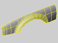
Density
Defines the number of isoparametric curves Rhino draws on the surface.
| Value | Display |
|---|---|
|
0 |
One isocurve at each knot; no isocurve in single-span cases. |
|
1 |
One isocurve at each knot; one isocurve in single-span cases. |
|
2 |
One isocurve at each knot; one extra isocurve between knot locations; one isocurve in single-span cases. |
|
3 |
One isocurve at each knot; two extra isocurves between knot locations; two isocurves in single-span cases. |
 Show surface isocurve
Turns display of surface isoparametric curves.
To change the default isoparametric curve density for new objects
- Go to Options > General.
Set the properties of the selected object to match properties of another object in the model.
See: MatchProperties
To match properties
- Select an object with the properties to match.
- Check the boxes for the properties to match.
Displays technical information of the selected object.
See: What.
Object Description
The object type: curve, surface, polysurface, block name, etc. displays.
Object ID
The object's internal identification number.
Layer name
The name of the layer assigned to the object.
Render Material
The name of the render material assigned to the object.
Source
Object, layer, or parent.
Index
The layer material index number.
Geometry
Details about the geometry mathematics, edges, vertices, and meshes.
-
When Model Units is Feet and Distance display is Decimal, Surveyor's Units (e.g., N 64°39'50" E 56.292') displays for line segments. Lines or polylines must be parallel to the World XY plane for Surveyor's Units to display.

SubD friendly information
When a curve or a surface is SubD friendly, its object description displays the information like:
Valid curve.
Open NURBS curve (SubD friendly)