ClippingPlane
| Toolbar | Menu |
|---|---|
|
|
View / Viewport title Clipping plane |
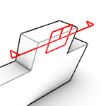
The ClippingPlane command creates a clipping plane object that represents a plane for visibly clipping away geometry in specified viewports.
![]() User's Guide - Architectural Drawings
User's Guide - Architectural Drawings
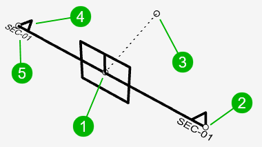
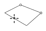
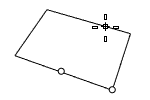
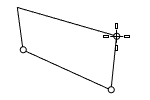
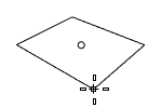
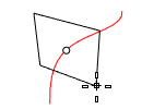
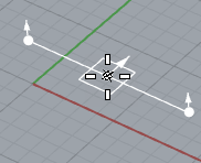
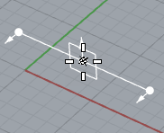
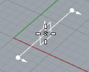
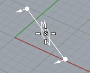
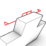
Components of a Clipping Plane widget
-
Translation point
Allows moving the Clipping Plane with object snaps in a viewport that is not clipped.
-
Scale point
Drag a scale point to re-size the widget.
-
Only visible when Custom Depth is enabled. The length of the dotted line is the depth distance.
-
The triangles point to the visible side of the clipping plane.
-
Label
Shows the name of the Clipping Plane in viewports. Details...
Steps
-
Pick two points for the opposite corners of a rectangle.
Or, select one of the options to draw the rectangle in a different way.
Command-line options
(Default)
Draws the rectangle using two opposite corners.
3Point
Draws the rectangle using two adjacent corner locations and a location on the opposite side.
EdgeMidpoint
Draws the rectangle from the midpoint of the first edge, an end of the edge, and a location on the opposite side.
Vertical
Draws the rectangle perpendicular to the construction plane.
Center
Draws the rectangle from the center point and a corner.
AroundCurve
Draws a rectangle perpendicular to a curve.
CustomDepth
Clips objects beyond the depth point.
Depth
The thickness of the visible portion of a clipped object in the model units.
Name
The name of the Clipping Plane.
-
Copies of a clipping plane with a name get incremental suffix numbers in their names.
Label
Displays the name in viewports if the Clipping Plane was given a name.
None
Do not display the name.
Dot
Displays the name as a Dot.
There is no control over the font and size for the dot labels.
Text
Displays the name as Text near the direction indicators.
The text label size is proportional to the widget size. The font of the current annotation style on Clipping Plane creation is applied.
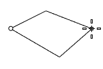
Custom Depth
Enable custom depth to limit the visible part of the clipped geometry to a specific distance from the plane.
For clipping planes with custom depth, turning on control points will show the depth point as well as the usual clipping plane control points. The custom depth can be adjusted interactively by moving this point.
Depth (Model Units)
Defines the thickness of the visible portion of the clipped object.
When the depth is set to 0, thin sections will be drawn.
Section Style
Specifies how to fill the clipping section on an object when the object has Section Style=By Clipping Plane set in its properties.
-
Colors of section styles override print colors.
By Layer
Uses the section style of the clipping plane's layer.
Custom
Uses the clipping plane's own section style set in the Section Style dialog.
Swaps the clipped and unclipped directions.
Objects Clipped
Controls clipping state by objects or layers independent from the view.
All
Clips all objects in clipped views.
Include Selected
Only clips the objects selected for custom clipping.
Exclude Selected
Only clips the objects not selected for custom clipping.
-
Click the button to add objects for custom clipping.
The number shows how many objects have been selected.
-
Click the
 button to clear the list.
-
Click the button to add layers for custom clipping.
The number shows how many layers have been selected.
-
Click the
button to clear the list.
Views Clipped
Lists all the viewports in the model. The checkboxes toggle the clipping state of the selected clipping plane in the viewports.
- The SelClippingPlaneInViewport command selects the clipping planes that clip the current model or detail viewport.
Model Space
Lists available model views.
Layout Space
Lists available layout and detail views.
- Detail views are grouped by pages.
- The
 icon indicates the currently enabled detail view.
 - Double-clicking a layout name makes it the current layout viewport.
- Double-clicking a detail view in the list activates the detail view.
Disables the current Clipping Plane in all viewports.
Copies the settings from another Clipping Plane.
Related commands
|
Toolbar |
Menu |
|---|---|
|
|
Drafting Sections > Create |
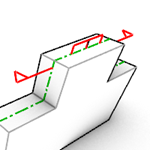
The ClippingSections command creates clipping planes that cut through selected objects with settings to define direction, depth, label, and save section views as Named Views.
Steps
-
Select objects to clip (press Enter to section through all objects).
-
Place one or more clipping sections in viewports.
During placement, the clipping widget turns red if it is not intersecting eligible objects' overall bounding box in World coordinates .
Command-line options for each clipping section can be set before placing it.
![]() User's Guide - Architectural Drawings
User's Guide - Architectural Drawings
Command-line options
Dir
Sets the clipping section direction.
CPlane 
The clipping section is parallel to the current CPlane.
X 
The clipping section is vertical to the current CPlane and parallel to the X-axis.
Y 
The clipping section is vertical to the current CPlane and parallel to the Y-axis.
Custom 
The clipping section is vertical to the current CPlane and parallel to the direction defined by two points.
CustomDepth
When set to No, the clipping plane depth is infinite. If set to Yes , the Depth option appears at the command-line, allowing the user to set the depth.
Depth
Defines the thickness of the visible portion of the clipped object. The default depth is zero.
Clip
Enable or disable clipping of the view that is active when the command starts. The views to be clipped can be set or modified in the clipping plane properties at any time.
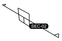
Name
Sets the prefix used for the section names. Section names are incremented, for example if you set the Name=SEC, sections are named: SEC_01, SEC_02, SEC_03, etc.
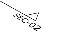
LabelMode
Sets how to display section names in viewports. The default label mode is Text.
None
Do not display the name.
Dot
Displays the name as a Dot.
There is no control over the font and size for the dot labels.
Text
Displays the name as Text near the direction indicators.
The text label size is proportional to the widget size. The font of the current annotation style on Clipping Plane creation is applied.
SaveToNamedView
Creates a named view that corresponds to a view of the section.
Note: Sections placed in a perspective viewport will generate named views in perspective projections, not parallel ones.
Flip
Swaps the clipping section direction.
See also
ClippingPlane
Create a plane that hides objects.
ClippingDrawings
Extracts sections and background geometry of clipping planes to generate 2D drawings on the World Top plane at the picked locations.
|
Toolbar |
Menu |
|---|---|
|
|
Drafting Sections > Clear All |
The ClearClippingSections command clears the clipping state of one or more clipping widgets in one or more views.
Steps
-
Select one or more clipping widgets.
Use the All option to select all visible clipping widgets.
-
Click in the viewport to disable its clipping state for selected clipping widgets.
Use the All option to disable all viewports.
|
Toolbar |
Menu |
|---|---|
|
|
Drafting Sections > Create Drawings |
The ClippingDrawings command extracts sections and background geometry of clipping planes to generate 2D drawings, then projects them to the World XY plane at the picked locations.
- The output drawings are organized by layers to help control visibility in modeling and layout spaces. Deleting a clipping plane also deletes the associated drawing and layers.
- Clipping drawings update interactively when the associated clipping planes are moved. If the clipped objects or their properties are changed, you have to use the UpdateClippingDrawings command to update the drawings.
Steps
-
Select one or more clipping planes.
Use the All option to create drawings for all visible clipping planes.
-
Pick placement point(s).
Press Enter to place the base point of the current drawing at the World Top origin.
-
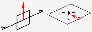
The arrow on the display feedback represents the "up" direction of the clipping plane.
-
The rectangle is the bounding box of the current section to assist with placement.
-
![]() User's Guide - Architectural Drawings
User's Guide - Architectural Drawings
Command-line options
Angle [Number]
The rotation angle of the current drawing.
-
Positive numbers rotate the drawings in the counterclockwise direction.
PrintWidth [ByLayer | ByInputObject]
ByLayer sets the drawings' print width to 'By Layer'; ByInputObject applies the sectioned object's print width to the drawings.
DisplayColor [ByLayer | ByInputObject]
ByLayer sets the drawings' display color to 'By Layer'; ByInputObject applies the sectioned object's display color to the drawings.
ShowHatch [Yes | No]
Controls whether hatches are created from clipping sections when the object's section style is set to display a hatch.
ShowSolid [Yes | No]
Controls whether planar surfaces are created from the clipping sections of solid objects.
AddBackground [Yes | No]
Projects the visible and hidden silhouette curves in front of the clipping plane.
-
The AddBackground option won't draw excluded objects or objects on excluded layers set in clipping plane properties.
Projection [Parallel | Perspective]
AddBackground=Yes only, sets the camera projection type to Parallel or Perspective. The camera location is set to the closest point on the clipping plane from the center of the bounding box of clipped objects.
SetTargetPoint
Projection=Perspective only, allows specifying the location of the camera target.
AddHidden [Yes | No]
Draws hidden curves on the background.
AddSilhouette [Yes|No]
Draws Silhouette curves on the background.
ShowLabel [Yes | No]
If Yes, then a text dot with the drawing name is added.
LabelStyle [Dot | Text]
Uses annotation dots or text to display labels.
Text labels use the current annotation style.
ApplyToAll [Yes | No]
Uses the current option settings for the rest drawings.
See also
ClippingPlane
Create a plane that hides objects.
ClippingSections
Creates clipping planes that cut through selected objects with settings to define direction, depth, label, and save section views as Named Views.
|
Toolbar |
Menu |
|---|---|
|
|

The ClippingPlaneProperties command manages the properties of a Clipping Plane in Command-line.
| Toolbar | Menu |
|---|---|
|
|
|
The DisableClippingPlane command turns off selected clipping planes in the active viewport.
| Toolbar | Menu |
|---|---|
|
|
|
The EnableClippingPlane command turns on selected clipping planes in the active viewport.
See also
|
Toolbar |
Menu |
|---|---|
|
|
Drafting Sections > Edit Drawings |
The EditClippingDrawings command allows updating the option settings for existing clipping drawings.
Steps
-
Select clipping planes.
Use the All option to select all visible clipping planes.
-
Edit the options of a clipping plane.
-
Press Enter to accept the changes and continue for the next clipping plane.
Command-line options
Angle [Number]
The rotation angle of the current drawing.
-
Positive numbers rotate the drawings in the counterclockwise direction.
PrintWidth [ByLayer | ByInputObject]
ByLayer sets the drawings' print width to 'By Layer'; ByInputObject applies the sectioned object's print width to the drawings.
DisplayColor [ByLayer | ByInputObject]
ByLayer sets the drawings' display color to 'By Layer'; ByInputObject applies the sectioned object's display color to the drawings.
ShowHatch [Yes | No]
Controls whether hatches are created from clipping sections when the object's section style is set to display a hatch.
ShowSolid [Yes | No]
Controls whether planar surfaces are created from the clipping sections of solid objects.
PlacementPoint
Moves the current drawing to another position.
- If you unlock the clipping drawing layers and move the drawings, they will return to the original positions when they are updated.
From
Allows precisely moving a clipping drawing with object snaps.
AddBackground [Yes | No]
Projects the visible and hidden silhouette curves in front of the clipping plane.
-
The AddBackground option won't draw excluded objects or objects on excluded layers set in clipping plane properties.
Projection [Parallel | Perspective]
AddBackground=Yes only, sets the camera projection type to Parallel or Perspective. The camera location is set to the closest point on the clipping plane from the center of the bounding box of clipped objects.
SetTargetPoint
Projection=Perspective only, allows specifying the location of the camera target.
AddHidden [Yes | No]
Draws hidden curves on the background.
AddSilhouette [Yes|No]
Draws Silhouette curves on the background.
ShowLabel [Yes | No]
If Yes, then a text dot with the drawing name is added.
LabelStyle [Dot | Text]
Uses annotation dots or text to display labels.
Text labels use the current annotation style.
ApplyToAll [Yes | No]
Uses the current option settings for the rest drawings.
See also
ClippingDrawings
Extracts sections and background geometry of clipping planes to generate 2D drawings on the World Top plane at the picked locations.
|
Toolbar |
Menu |
|---|---|
|
|
Drafting Sections > Export Drawings |
The ExportClippingDrawings command saves clipping drawings of selected clipping planes to separate Rhino (.3dm) or .dwg files.
- If the selected clipping plane already has its drawing (created by the ClippingDrawings command) in the model, the existing drawing is exported directly. Otherwise the drawing will be created on the fly to export.
- The clipping plane names are used to save the files.
Steps
-
Select clipping planes.
Use the All option to select all visible clipping planes.
Command-line options
Folder
Sets the folder for saving the drawing files.
Extension [3dm | dwg]
Specifies the file format to save.
|
Toolbar |
Menu |
|---|---|
|
|
Drafting Sections > Export Info |
The ExportClippingSectionInfo command creates a .csv file listing sections with basic location and area calculations for sections that have clipping drawings associated with them.
Steps
-
Specify the file name and location.
All sections that have associated drawings are exported.
|
Toolbar |
Menu |
|---|---|
|
|
Drafting Sections > Extract Sections |
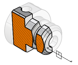
The ExtractClippingSections command duplicates the section boundaries and fills from the objects clipped by the selected clipping plane as curves and hatches.
- The ExtractClippingSections command only extracts thin sections from objects. The ExtractClippingSlices command provides options to extract sections with a thickness.
Steps
-
Select one or multiple clipping planes.
Command-line options
Curve [Yes | No]
Specifies whether section boundaries will be extracted as curves.
Hatch [Yes | No]
Specifies whether section fills will be extracted as hatches.
Group [Yes | No]
Specifies whether output objects will be grouped.
|
Toolbar |
Menu |
|---|---|
|
|
Drafting Sections > Extract Slices |
The ExtractClippingSlices command extracts 3D slices of clipped model objects from clipping planes.
There is no output from objects that do not make a fully closed intersection with the clipping plane.
Steps
-
Select one or multiple clipping planes, and press Enter.
The output slices could be NURBS or mesh objects depending upon the clipped object type.
Command-line options
UseClippingPlaneDepth
Extracts the slices using the custom depth set in Clipping Plane properties as the thickness.
-
When the custom depth is disabled, 0 is used as the thickness.
-
UseClippingPlaneDepth=Yes hides the Thickness and Location options.
Thickness
Specifies the slice thickness.
If the thickness is 0, planar slices are returned. Otherwise, 3D solids are returned.
Location
The location of the slice relative to the clipping plane.
Front
Creates the slice in front of the clipping widget.
The triangles point to the front direction.
Center
Creates the slice with the clipping widget on the center plane.
Back
Creates the slice behind the clipping widget.
Group
Specifies whether output objects will be grouped.
|
Toolbar |
Menu |
|---|---|
|
|
Drafting Sections > Nested Drawings |
The NestedClippingDrawing command projects object sections from 3D space to the World XY-plane, on the current layer, with user-specified spacing and arrangement. The output is static snapshots of the section layouts that do not update with section changes.
Steps
-
Select clipping planes.
Use the All option to create drawings from all visible clipping planes.
The All option creates drawings ordered by section names in alphabetical order.
-
Pick the base point to place the first drawing.
The other drawings will be arranged according to the option settings.
Command-line options
ShowSolid [Yes|No]
Creates planar surfaces from the clipping sections of solid objects.
Arrangement [WorldX|WorldY]
Arranges the layouts horizontally along the World X axis or vertically along the World Y axis.
Spacing [Number]
Specifies the gap, in model units, between projected drawings.
Width [Number]
When Arrangement=WorldX, the width value, in model units, restricts how many drawings can fit in one row. New rows are added as needed to accommodate all of the drawings.
ShowLabel [Yes|No]
Adds section names to the drawings.
ShowLabel=Yes adds the LabelStyle and LabelLocation options.
LabelStyle [Dot|Text]
Sets the type of labels to Text or Dot.
LabelLocation [Outside|Inside]
Locates labels outside or inside the drawings.
See also
ClippingSections
Creates clipping planes that cut through selected objects with settings to define direction, depth, label, and save section views as Named Views.
|
Toolbar |
Menu |
|---|---|
|
|
Drafting Sections > Save CPlanes |
The SaveClippingSectionCPlanes command saves Named CPlanes using the names and orientations of selected clipping planes.
-
The saved CPlane is named according to the clipping plane name.
-
The saved Named CPlane updates when the associated clipping plane is moved.
-
Deleting a clipping plane also deletes the corresponding Named CPlane, but not the other way around.
Steps
-
Select the clipping plane(s).
Select the All option to save Named CPlanes from all visible clipping planes.
|
Toolbar |
Menu |
|---|---|
|
|
Drafting Sections > Save Views |
The SaveClippingSectionViews command saves the views of selected clipping sections to the Named Views panel.
-
The saved view is named according to the clipping plane name.
-
The saved Named View updates when the associated clipping plane is moved.
-
Deleting a clipping plane also deletes the corresponding Named View, but not the other way around.
Steps
-
Select the clipping plane.
Select the All option to save Named Views from all visible clipping planes.
-
Set command-line options.
Command-line options
Projection [Parallel|Perspective]
Sets the saved view projection to Parallel or Perspective.
Clip [Yes|No]
Clips the saved view with the clipping plane.
SetCPlane [Yes|No]
Sets the CPlane of the saved view to the section plane.
|
Toolbar |
Menu |
|---|---|
|
|
Drafting Sections > Update Drawings |
The UpdateClippingDrawings command updates clipping drawings to reflect changes in the clipped geometry.
-
Dynamic clipping drawings update automatically when transforming the clipping planes, but when clipped objects are edited or new objects are added, the update is not automatic.
Steps
-
Select the clipping planes that you would like to update their drawings.
Use the All option to update drawings for all visible clipping planes.
|
Toolbar |
Menu |
|---|---|
|
|
Drafting Sections > View |
The ViewClippingSections command aligns the view and/or construction plane of a viewport to match the selected clipping section plane.
Steps
-
Select one or more clipping planes.
Use the All option to select all visible clipping planes.
-
Select a viewport for each of the selected planes.
Command-line options
Clip [Yes|No]
Clips selected section in the selected view.
The viewport is enabled in the properties of the clipping plane.
ClearOtherSections [Yes|No]
Unclips all other sections.
The viewport is disabled in the properties of all other clipping planes.
SetView [Yes|No]
Orients the view to align with the clipping plane.
SetCPlane [Yes|No]
Orients the CPlane to align with the clipping plane.