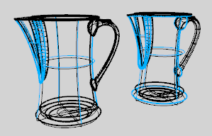
The Wireframe display mode sets the viewport display to unshaded wireframe.
 Include in View's display menu
Displays the custom display mode in the viewport title and View menus.
 Include in Shade command modes
Offers the custom display mode as an option for the Shade command.
 Allow assignment to individual objects
Allows applying this display mode to objects with the SetObjectDisplayMode command.
Specifies the viewport background color.
Use application settings
Use settings specified in Appearance > Color Options.
Solid color
| 4 | Click the color swatch to select a color. |
Image file
Specifies an image for the viewport background.
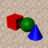
Image file name
| 4 | Type or browse for the file name. |
Gradient 2 colors
Blends between a top and bottom color.
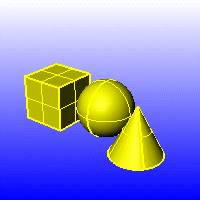
Top color / Bottom color
| 4 | Click the color swatch to select a color. |
Gradient 4 colors
Blends between four colors starting from the corners of the viewport.
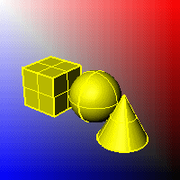
Top left color / Top right color / Bottom left color / Bottom right color
| 4 | Click the color swatch to select a color. |
Use render settings
Displays the colors and lighting used by the settings for background specified by the current renderer.
透明
Renders viewport backgrounds using black and a 0.0% alpha value. This works for rendered output and for ViewCaptureToFile.
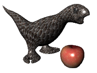
Specifies which elements will be visible in the display mode.
 Show isocurves
Shows object isocurves.
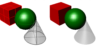
Isocurves on (left) and off (right).
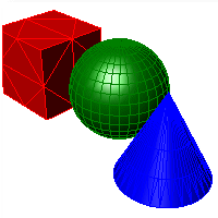
 Show mesh wires
Shows mesh wires.
 Show curves
Shows curves objects.
 Show lights
Shows lights objects
 Show clipping planes
Shows clipping planes objects.
 Show text
Shows text blocks.
 Show annotations
Shows annotations objects.
 显示点
显示点
Shows points objects.
 Show pointclouds
Shows pointclouds objects
Edge thickness
Sets the thickness in pixels for surface edges.
Color reduction %
Sets the "fade" effect for surface edges.
 Use lights on layers that are off
This setting applies to lights that are on turned-off layers and lights that are hidden.
 Draw lights using light color
Draws lights using the color of the light rather than the color of the light object.
The lighting used by the display mode.
Lighting method
No lighting
No shading occurs when there is no light sources added to the scene.

Scene lighting (left), No lighting (right).
Default lighting
Uses a single "head lamp" light.
Scene lighting
Uses the light objects that exist in the current model/scene.
Custom lighting
Sets up to eight custom lights.
Set an x-, y-, and z-direction and color for each light.
Light #
Up to eight lights are available.
方向
Setting the directional value to 0,0,0 disables the light.
Color
The color the light shines on objects.
Specular
The highlight color the light creates on glossy objects.
Identifies any lights in the scene that are Directional lights, and uses up to eight lights to populate the fields in the dialog.
附注
| ● | This option deletes all current values in the dialog, even if there were no directional lights found in the scene. |
| ● | The directional lights are converted to camera-directional lights using world-coordinates. |
Applies the lighting to the model.
Ambient color
| 4 | Click the color swatch to select a color. |
 Use advanced GPU lighting
With normal, per-vertex lighting, calculations only occur for each vertex in a mesh. Everything else in between is interpolated (invented).
This has major limitations for shading, lighting, and texturing, especially when a mesh has very few vertices. For example, a plane with four vertices, has nothing to interpolate over the plane surface. When only vertices are used, there is very little data.
With Advanced GPU (per-pixel) lighting, calculations occur for every pixel within the viewport, no matter how many vertices there are. This gives more data, and the larger the frame buffer, the more detail and data you get. The result is that you can now light the entire plane and see how light falls across the entire surface independent of how many vertices there are.
![]()
Advanced GPU lighting on (left) and off (right).
附注
| ● | In order to display bump mapping in Rendered mode, the Use Advanced GPU lighting setting must be checked. |
Specifies how clipping plane objects appear in the display mode.
 Show fills (shaded modes only)
When a clipping plane intersects a 3-D object, the object is filled.
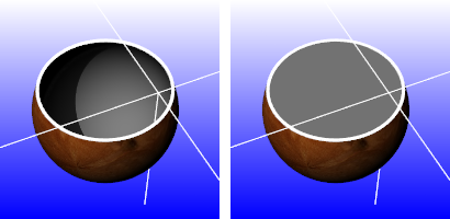
Fills off (left) and on (right).
Color usage
Specifies how the color for the clipping plane object fill is determined.
工作视窗
Uses the viewport background color.
Render material
Uses the clipping plane's render material.
Plane's material
Uses the clipping plane's color or layer color property.
Solid color
| 4 | Click the color swatch to select a color. |
 显示边缘
显示边缘
Shows the edges between the clipping plane and clipped objects.
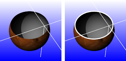
Edges off (left) and on (right).
Color usage
Plane's color
Uses the clipping plane's color (object or layer).
Solid color
| 4 | Click the color swatch to select a color. |
Edge thickness
Edge thickness in pixels.
 Shade selected plane
Shades the selected clipping plane.
Color usage
Plane's color
Uses the clipping plane's color (object or layer).
Plane's material
Uses the plane's render material (object or layer).
Solid color
| 4 | Click the color swatch to select a color. |
Transparency %
Specifies the clipping plane transparency.
 Clip selection highlight
Clips the highlight wires. Shaded selections always clip.
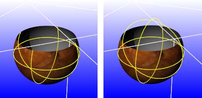
Selection highlight clipped (left) and not clipped (right).
Use document settings
Use settings specified in Grid Document Properties.
Use mode-specific settings
Specify the settings in individual modes.
Show grid
Show grid axes
Show world axis icon
Application settings
Use default setting.
Same as grid axis colors
Set colors for grid axes in Appearance: Colors Options.
Use specified custom colors
| 4 | Click the color swatch to select a color. |
Display construction plane z-axis.
Axes size (grid extent %)
Set size of axes as a percentage of the grid extents.
Grid appearance
Show grid behind / on top of all objects
Shows the grid behind all objects or allows the grid to pass through objects.
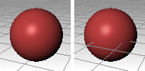
Grid behind (left) and on top of objects (right).
Displays the grid lines with transparency.
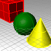
Transparency %
Do not use / use transparent plane
Displays the grid as lines or as a transparent plane with lines.
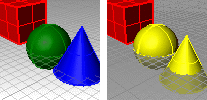
Do not use transparent plane (left) and Use transparent plane (right).
Plane color
| 4 | Click the color swatch to select a color. |
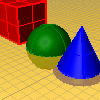
Plane transparency %
Plane visibility
Show only when grid is on
Show always
Use dotted / solid lines
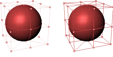
Dotted (left) and solid control polygon ( right).
The width of the control polygon in pixels.
Control polygon color
Specifies a color for the control polygon.
Use object color
Use the color specified in the object's Properties.
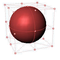
Use fixed color
Use a specified color for all control polygons.
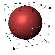
Polygon color
| 4 | Click the color swatch to select a color. |
可见性
 隐藏控制点
隐藏控制点
Hides the control points while the control polygon is displayed.
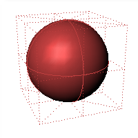
 Hide object
Hides the object while the control polygon is displayed.
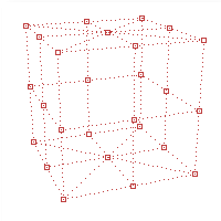
 Hide control polygon
Hides the control polygon and only shows the control points.
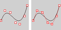
Hide control polygon on (left) and off (right).
 Highlight control polygon
Highlights the segments of the control polygon on either side of the control points.
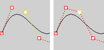
Highlight control polygon on (left) and off (right).
Control point size
The control point size in pixels.
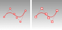
Size = 2 (left), size = 3 (right).
锁定的物件
Use application settings
Use settings specified in Appearance: Colors Options.
Use specified lock color
| 4 | Click the color swatch to select a color. |
Use object's display attributes
Uses the object's specified attributes.
Locked object appearance
Locked objects appear solid
Locked objects appear transparent
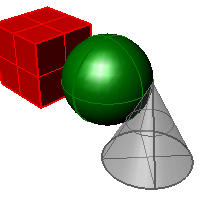
Gray locked object transparent.
Transparency %
Sets the amount of transparency as a percentage.
 Draw objects behind all others
Draws locked objects behind all other objects.
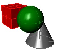
Gray locked object displayed behind others.
 Apply these settings to layers
Applies the settings for locked objects to locked layers.
Dynamic usage
Sets the appearance of objects in the display
Use application settings
Use system default settings.
Display object's bounding box
Reduces the display of objects to their bounding boxes. This can speed up the display on large models.
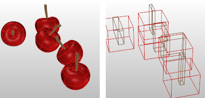
Bounding box display off (left) and on (right).
Always display
Always display objects as bounding boxes.
Only display during view changes
Change objects to bounding boxes only when zooming or panning.
Point style
Specifies the appearance of point objects.
Square with white center
Displays point objects as squares with a white center.
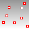
Size
Point object size in pixels.
Solid square
Displays point objects as a solid squares.
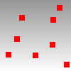
Size
Point size in pixels.
PointCloud style
Specifies the appearance of point cloud objects.
Square with white center
Displays point cloud objects as squares with a white center.

Size
Point cloud point size in pixels.
Solid square
Displays point cloud objects as a solid squares.

Size
Point cloud point size in pixels.
PointCloud control point style
Specifies the appearance of point cloud control points.
Square with white center
Displays point cloud control points as squares with a white center.

Size
Point cloud point control point size in pixels.
Solid square
Displays point cloud control points as a solid squares.

Size
Point cloud point size in pixels.
Curve color usage
Specifies a color for all curves.
Use object's color
Use the color specified in the curve's Properties.
Use single color for all curves
Use the specified color for all curves.
Curve color
| 4 | Click the color swatch to select a color. |
Curve width
Specify the curve width in pixels.
Edge color usage
Specifies a color for surface edges.
Use object's color
Use the color specified in the object's Properties.
Use isocurve color
Use a color specified for isocurves.
Use single color for all edges
Use the color specified for all surface edges.
边缘颜色
| 4 | Click the color swatch to select a color. |
Naked Edge usage
Specifies a color for naked (unjoined) surface edges.
Use edge settings
Use the same color as specified for edges.
Use separate settings for naked edges
Use a specified color for all naked edges.
Edge thickness
The edge width in pixels.
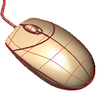
Edge thickness = 3 pixels.
Color reduction %
Lightens the color by a percentage.
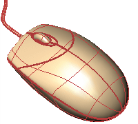
Edge color reduction 50%.
Edge color usage
Specifies a color for surface edges
Use object's color
Use the color specified in the object's Properties.
Use isocurve color
Use the color specified for the isocurves.
Use single color for all naked edges
Specifies a color for all naked surface edges.
Naked edge color
| 4 | Click the color swatch to select a color. |
Isocurve color usage
Specifies a color for surface isocurves.
Use object's color
Use the color specified in the object's Properties.
Use single color for all isocurves
Specifies a color for all isocurves.
Isocurve color
| 4 | Click the color swatch to select a color. |
Use specified UV colors
Use separate colors for u- and v-isocurves.
U Color/V Color
| 4 | Click the color swatch to select a color. |
Isocurve width
Specifies a width for surface isocurves.
Use single width for all isocurves
Specifies a width for all surface isocurves.
Isocurve width
Specifies a width for surface isocurves in pixels.
Use specified UV widths
Use separate widths for u- and v-isocurves.
U width/V width
Specifies the width for u- and v-isocurves in pixels.
Wireframe color usage
Specifies a color of the mesh wires.
Use object's color
Use the color specified in the object's Properties.
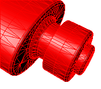
Use single color for all meshes
Specifies a color for all mesh wires.
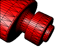
Wireframe color
| 4 | Click the color swatch to select a color. |
Wireframe thickness
Mesh wire width in pixels.
Vertex size
Mesh vertex size in pixels.
Edge color usage
Specifies a color for mesh edges.
Use object's color
Use the color specified in the object's Properties.
Use single color for all edges
Specifies a color for all mesh edges.
边缘颜色
| 4 | Click the color swatch to select a color. |
Edge thickness
Mesh edge width in pixels.
Color reduction %
Make the color lighter by a percentage.
Edge color usage
Specify a color for all naked mesh edges.
Use object's color
Use the color specified in the object's Properties.
Use single color for all naked edges
Specify the color for all naked mesh edges.
边缘颜色
| 4 | Click the color swatch to select a color. |
Edge thickness
Naked mesh edge width in pixels.
Color reduction %
Make the color lighter by a percentage.
Edge color usage
Specify a color for non-manifold mesh edges.
Use object's color
Use the color specified in the object's Properties.
Use single color for all non-manifold edges
Specify the color for all non-manifold mesh edges.
边缘颜色
| 4 | Click the color swatch to select a color. |
Edge thickness
Non-manifold mesh edge width in pixels.
Color reduction %
Make the color lighter by a percentage.
Shadows off / Shadows on
Video memory usage / shadow size
Minimum (grainy shadows)![]() Maximum (sharper shadows)
Maximum (sharper shadows)
Soft edge quality / speed
None / faster![]() Softer / slower
Softer / slower
Edge blurring
No blurring![]() Maximum blurring
Maximum blurring
Self shadowing artifacts
Dirty![]() Cleaner
Cleaner
Transparent objects
Never cast shadows![]() Always cast shadows
Always cast shadows
Camera based clipping bubble
None![]() Maximum radius
Maximum radius
Shadow color
| 4 | Click the color swatch to select a color. |
 Shadows ignore user-defined clipping planes
Horizontal scale
Expands the view and grid horizontally.
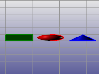
Vertical scale
Expands the view and grid vertically.
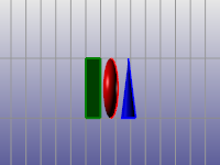
Stereo viewing is display-mode specific. Once a display mode is configured to operate in stereo mode, all views that are in that mode will also be viewed in stereo.
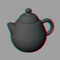
Stereo modes use what is called asymmetry stereo.
It is best to make a copy of an Advanced Display mode and turn on the Stereo mode settings for this copied view.
附注
| ● | To see if a system supports 3-D shutter glasses, select a stereo display mode. |
| ● | This should cause your view to have two rapidly flickering images. The view will appear almost blurry because of the two slightly offset copies of the viewport image. If you do not see this, and the view looks the same as any other view, then either the refresh rate is not set high enough or the video card does not support it. |
| ● | Video cards designed for games may support hardware stereo mode in DirectX, but not in OpenGL. |
Stereo usage
Stereo mode disabled
Use hardware 3D shutter glasses
Requires three forms of special hardware:
| ● | A video card and drivers that support OpenGL stereo modes |
| ● | A monitor that can support a refresh rate of 100hz or higher |
| ● | A pair of 3-D shutter glasses that can plug in to the back of your special video card. |
Separation
Parallax
Use anaglyph glasses
A pair of red/blue anaglyph glasses like those that you get at a 3-D movie is required.
Separation
Parallax
Color usage
Use black and white imaging
Use full-color imaging
Glasses configuration
Red and Cyan glasses
Red and Blue glasses
Red and Green glasses
Amber and Blue glasses
Flip left and right lenses
请参考