Weld 指令将组合在一起的数个顶点合并为单一顶点。
Individual texture mapping, color, and normal vector data is averaged/created/destroyed for the affected vertices.
网格顶点熔接后由一个以上的网格面共用,顶点的法线为相邻的网格面的法线的平均值。
指令行选项
角度公差
如果同一个网格的不同边缘有顶点重叠在一起,而且网格边缘两侧的网格面法线之间的角度小于角度公差设定值,重叠的顶点会以单一顶点取代。不同网格组合而成的多重网格在熔接顶点以后会变成单一网格。
改变角度公差时公差范围内将被熔接的边缘会以醒目提示。
The WeldEdge command removes creases from a mesh by merging coincident mesh vertices along selected edges.
指令行选项
Undo
取消最后选取的边缘
The WeldVertices command removes creases from a mesh by merging all selected mesh vertices.
您可以使用 WeldVertices 指令只熔接选取的网格顶点,而不必熔接整个网格,但这个指令没有与 Weld 指令一样的熔接角度公差设定。您可以打开网格的顶点,使用框选预选要熔接的网格顶点再执行指令,或先执行指令再点选个别的网格顶点。
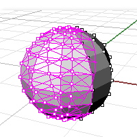
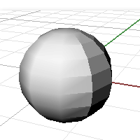
网格顶点
顶点是网格面边缘的汇集点,网格顶点(复数顶点)包含 X、Y、Z 座标,也可能包含法线向量、色彩值及贴图座标。
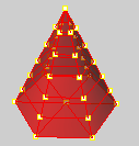
是否熔接网格顶点会影响渲染、网格上的贴图对应及导出给快速成型机的文件。
在线框模式下,这两个网格物件看起来没有什么不同。
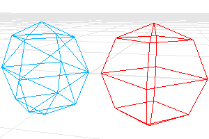
在渲染模式下,红色的网格看起来比较平滑,而蓝色的网格有明显网格边缘。
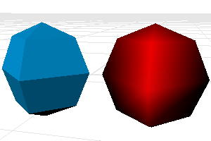
因为红色网格上的顶点都熔接在一起,所以看起来比较平滑。蓝色网格的顶点只是重叠在一起,并未熔接,所以每一个网格面的边缘都清晰可见。
如果您想要让蓝色的网格看起来与红色的网格一样平滑。
First you have to determine the angle tolerance. The shaded creases of this angle should look sharp.
贴图如何包覆在物件上是由贴图座标所控制,贴图座标会将贴图的 2D 座标对应至网格顶点,然后依据顶点的数值将贴图影像插入在相邻的顶点之间。
点阵图的左下角为原点,右下角的座标为 (1,0),左上角的座标为 (0,1),右上角的座标不 (1,1),贴图座标的数值永远都在这些数值以内。
每一个顶点只能含有一组贴图座标,重叠的几个顶点含有的几组贴图座标在熔接后只有一组贴图座标会被留下来。
当一个网格的贴图座标遗失后,您无法从该网格复原遗失的贴图座标。
使用 UnWeld 或 UnWeldEdge 指令解除熔接网格时,网格的贴图座标也会被移除。
某些快速成型机只能读取完全封闭 (水密) 的 STL 网格文件。
在导出快速成型机使用的 STL 文件之前,您可以使用以下的流程确保导出的是有效的 STL 文件:以 Join 指令组合个别的网格。以 Weld 指令 (角度公差 = 180) 熔接组合后的网格。以 UnifyMeshNormals 指令统一网格法线,建立单一的封闭网格。以 SelNakedMeshEdgePt 指令检查网格是否完全封闭 (没有外露边缘)。
See: Stereolithography (.stl) Import/Export.
Unweld 指令将数个网格面的共用顶点解除熔接。
指令行选项
ModifyNormals=Yes/No
If Yes, the vertex normals on each side of the edge take the same value as the face to which they belong, giving the mesh a hard edge look.
If No, each of the vertex normals on either side of the edge is assigned the same value as the original normal that the pair is replacing, keeping a smooth look.
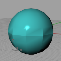
UnweldEdge 指令将选取的网格边缘的顶点分离。
指令行选项
ModifyNormals=Yes/No
If Yes, the vertex normals on each side of the edge take the same value as the face to which they belong, giving the mesh a hard edge look.
If No, each of the vertex normals on either side of the edge is assigned the same value as the original normal that the pair is replacing, keeping a smooth look.
网格是由两个清单定义:
| ● | 一个是顶点的清单,内含顶点的属性 (位置、法线、贴图座标、顶点色)。 |
| ● | 另一个是面的清单,用来描述顶点如何连接形成面。 |
四角网格面
以下是描述图中两个独立的四角网格面的两个清单。
顶点清单
The vertex list is half of the mesh definition, describing the vertices.
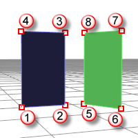
Note: In this example texture coordinates and vertex colors are left out, but those are per-vertex attributes as well.
顶点 1 : 位置, 法线
顶点 2 : 位置, 法线
顶点 3 : 位置, 法线
顶点 4 : 位置, 法线
顶点 5 : 位置, 法线
顶点 6 : 位置, 法线
顶点 7 : 位置, 法线
顶点 8 : 位置, 法线
面的定义
This list describes how these vertices are connected to form faces.
面 1 : 顶点 1, 顶点 2, 顶点 3, 顶点 4
面 2 : 顶点 5, 顶点 6, 顶点 7, 顶点 8
三角网格面的例子 1
以下是描述图中两个独立的三角网格面的两个清单。
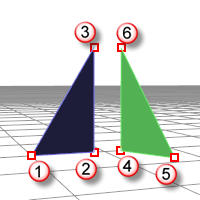
顶点 1 : 位置, 法线
顶点 2 : 位置, 法线
顶点 3 : 位置, 法线
顶点 4 : 位置, 法线
顶点 5 : 位置, 法线
顶点 6 : 位置, 法线
面 1 : 顶点 1, 顶点 2, 顶点 3
面 2 : 顶点 4, 顶点 5, 顶点 6
三角网格面的例子 2
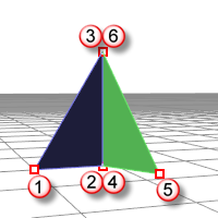
In the next example, imagine two of those six vertices share the same position:
顶点 1 : 位置, 法线
顶点 2 : 位置, 法线
顶点 3 : 位置, 法线
顶点 4 : 位置, 法线
顶点 5 : 位置, 法线
顶点 6 : 位置, 法线
面 1 : 顶点 1, 顶点 2, 顶点 3
面 2 : 顶点 4, 顶点 5, 顶点 6
这个例子中的顶点 2 与 4 在同一个位置,顶点 3 与 6 也在同一个位置。
这两个面有一个共同的边缘,但是顶点 2、3、4、6 都有自己的属性,所以这些顶点都有独立的法线方向。
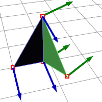
组合的网格
When you Join a mesh, the vertices and faces are in no way merged; the lists are simply appended. The face normals retain their direction.
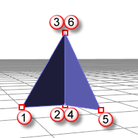
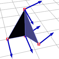
Welded mesh
When you Weld a mesh and the angle between the faces is below the threshold the common edge will be welded.
相同位置的顶点会被一个新的顶点与新的属性取代:
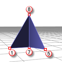
顶点 1 : 位置, 法线
顶点 5 : 位置, 法线
顶点 7 : 位置, 法线
顶点 8 : 位置, 法线
面 1 : 顶点 1, 顶点 7, 顶点 8
面 2 : 顶点 7, 顶点 5, 顶点 8
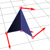
顶点 7 与 8 的法线是两个面的法线平均值,所以熔接过后原来的顶点法线就再也无法复原了。
结论
| ● | 组合不会破坏网格顶点的任何属性资讯。 |
| ● | 熔接会重新计算网格顶点的所有属性资讯。 |
| ● | The resulting new vertex has it's normal calculated based on the average of the faces it belongs to. |
请参考