Tools > Options > View > Display Modes
The Display modes options manage the appearance of the viewport display modes.
The built-in display modes are:
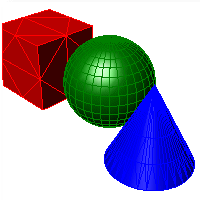
Sets the viewport display to unshaded wireframe. 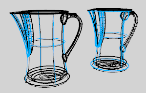
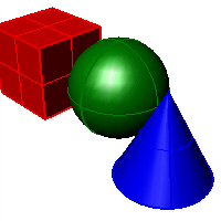
Sets the viewport to opaque shaded mode. Shaded mode uses a mesh to shade surfaces using the layer colors.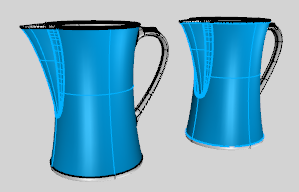
Sets the viewport to a raytraced render preview mode.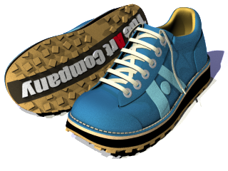
Shades the viewport with a simulation of the rendered view.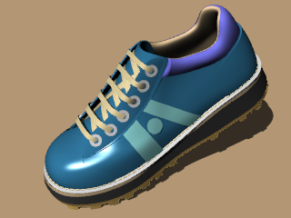
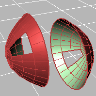
Sets viewport display so surfaces are translucent.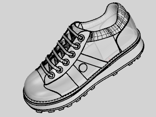
Shades with isoparametric curves not obscured by objects in front.
All wireframe and point objects are displayed, even if they would normally be hidden by surfaces that are in front of them in the viewport.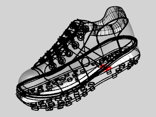
Uses real-time silhouettes and intersections, creases, borders, blended shaded and rendered display. Objects behind other objects are occluded. 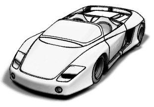
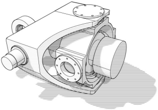
Uses an image background and soft lines to create a pencil drawing effect.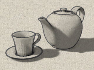
Uses white with black lines to simulate a pen drawing.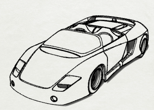
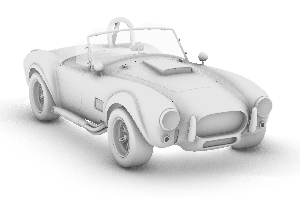
Uses white for all objects and the background with soft shadows to give the feeling of the Arctic.
Create a new custom display mode.
Copy a display mode.
Delete a custom display mode.
Import a display mode (.ini) file.
Export a display mode.
Restores the default system values. All custom display mode settings will be lost.
Not all of the settings described below are available for all display modes.
Name of display mode.
Specifies the viewport background color.
Use settings specified in Appearance > Color Options.
Specifies an image for the viewport background.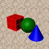
Blends between a top and bottom color.
Blends between four colors starting from the corners of the viewport.
Displays the colors and lighting used by the settings for background specified by the current renderer.
Renders viewport backgrounds using black and a 0.0% alpha value. This works for rendered output and for ViewCaptureToFile. ![]()
Sets the viewport to opaque shaded mode.
Shades with isocurves not obscured by objects in front.
Shades the current viewport with no smoothing so the individual render mesh faces are visible. 
See: FlatShade.
Shades using an object's vertex colors.
See: ComputeVertexColors .
Ignores object colors and uses a single color for the shading.
Sets the gloss for the color.
Sets the transparency for the color.
Shades using rendering material.
Click the button to specify the custom material.
Opens the Custom Object Attributes Settings dialog box.
Changes the color of the backface (the side opposite of the surface normal direction).
No color change.
Surfaces viewed from the back will be transparent.
Surfaces viewed from the back use the color specified in the object's Properties.
Sets the gloss for the backface material. This can be different from the front face material.
Sets the transparency for the backface material. This can be different from the front face material.
All backfaces display a specified color regardless of the object color.
Sets the gloss for the backface material. This can be different from the front face material.
Sets the transparency for the backface material. This can be different from the front face material.
Sets a single color for all backfaces.
Shades using rendering material.
Click the button to specify the custom material.
Opens the Custom Object Attributes Settings dialog box.
Uses normal solid shading.
Uses parallel lines for shading.
Width of the lines.
Distance between lines.
Rotation angle of lines.
Specifies which elements will be visible in the display mode.
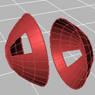
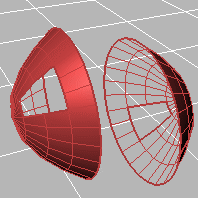
Shows object isocurves.
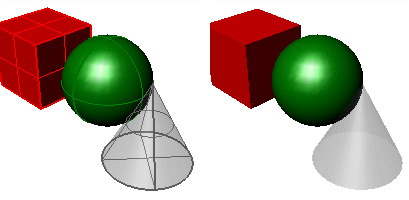
Isocurves on (left) and off (right).
Tangent polysurface edges are smooth edges between different faces of a polysurface.
Tangent seams are smooth edges that close surfaces such spheres or cylinders.
Shows mesh wires.
Toggles visibility of welded mesh edges.
Shows curves objects.
Shows lights objects
Shows clipping planes objects.
Shows text blocks.
Shows annotations objects.
Shows points objects.
Shows pointclouds objects
Sets the thickness in pixels for surface edges.
Sets the "fade" effect for surface edges.
This setting applies to lights that are on turned-off layers and lights that are hidden.
Draws lights using the color of the light rather than the color of the light object.
See Lighting scheme settings.
See Clipping plane settings.
See Objects settings.
See Points Settings.
See Curves Settings.
See Surfaces settings.
See Meshes settings.
See Lines settings.
See Shadows settings.
See Other Settings.
Save Options settings to a file.
Restore Options settings from a file.
| Toolbar | Menu | Shortcuts |
|---|---|---|
|
|
|
G Ghosted R Rendered S Shaded W Wireframe X XRay |
The SetDisplayMode command specifies a display mode.
To set a mode name that has spaces, use either of the following formats:
-_SetDisplayMode Mode=MyMode
-_SetDisplayMode "My Mode"
| Command-line options | |
|---|---|
|
Viewport |
ActiveSets the display mode for only the active viewport. AllSets the display mode for all viewports. |
|
Mode |
Lists all of the current display modes in the model. |
Create custom display modes in Rhino 6
Rhinoceros 6 © 2010-2020 Robert McNeel & Associates. 11-Nov-2020