![]()
Render
Texture Editor
Panels
Textures
Textures
| Toolbar | Menu | Panel Gear Menu |
|---|---|---|
|
|
Render Texture Editor Panels Textures |
Textures |
The Textures command opens the Textures panel that creates textures that can be dragged and dropped onto Materials and Environments controls.
![]() Textures panel
Textures panel
The Textures panel has additional browsing tools.
Selects the previous item in the list.
Selects the next item in the list.
Displays the current item icon and name.
Limits the search to names.
Limits the search to notes.
Limits the search to tags.
Displays how 'name:', 'note:', 'tag:', '?', '#' and '^' are used for searching items.
Displays the Tools menu.
Imports materials from a saved Rhino .rtex file.
Specifies the texture type.
Opens the content type browser to see more options for creating a new texture.
Each texture type has its own set of settings appropriate for the type.
In addition to the settings specific to the texture type, the following settings sub-panels appear when appropriate.
The name of the texture.
This setting displays whenever colors can be specified for the texture components.
The color for each component of the material can be set to a different color or texture.

 or right-click the swatch to open the context menu.
Opens the Select Color dialog box.
Allows picking the color from anywhere on the screen.
Copies the color in the color swatch.
Pastes the color from one color swatch to another.
Assign a texture to the color control.
Opens the texture editor.
Removes the texture from the control.
Assign an image or a procedural texture to use as the color.
Select an image file or click and select a procedural texture type.
 Browse
Opens the Bitmap Texture Settings panel.
Copies the image to the clipboard.
Pastes the image in the clipboard into the texture slot.
Pastes the image in the clipboard as an instance. Changes to the parent image also change the instances.
Opens a floating thumbnail preview of the texture.
Select a different image or texture type.
Removes the texture from the slot.
Removes the instancing, breaking the connection to the original parent image.
Opens the Properties dialog box for setting the output channel.
Properties
Exchanges colors 1 and 2 for each other.
Tries to reduce aliasing in the texture.
See: Wikipedia, Supersampling.
You can drag the color swatch to a folder to create a Rhino color file.
Determines how colors at the original uv(w) coordinates of the texture are translated to the uv location on an object. The Rhino default is to use the uv coordinates given by the geometry itself: either the parameters of the surface or the original texture coordinates of the mesh. These controls allow modification of the way the texture appears to wrap itself around objects.
Shifts the texture along the u and/or v direction in texture space.
Causes the texture to recur in texture space.
Rotates the texture in texture space by a specific number of degrees.
UV coordinates are generated from the actual position in world space of the object. This is useful for real-world size materials - especially 3‑D procedural textures.
UV coordinates are generated from a coordinate system specified by the world space location on the object and the side of an imaginary box pointed to by the object’s normal at that location. This is useful for real-world style materials, particularly 2‑D types like bitmaps, since the sides of objects will also be projected in a meaningful manner.
Uses the texture coordinates of that object on a specific mapping channel. By default, with a single mapping channel in use on an object, the texture coordinates will be generated from values found in Object Properties > Texture Mapping.
Uses a 3-D object in the thumbnail and preview window to display the mapping on an object. See: Textures panel thumbnail context menu.
If this checkbox is on, texture previews will be modified by the mapping parameters. This can make it difficult to see the texture itself, if there is a high repeat, for example.
Displays the results of mapping a texture when that texture is not well displayed in the viewport. The texture is displayed temporarily as if it were the object color. This can be useful with advanced rendering engines where the viewport display does not support a particular rendering feature that can be textured (for example, reflectivity).
Determines how colors at the original uv(w) coordinates of the texture are translated to the uv location on an object. The Rhino default is to use the uv coordinates given by the geometry itself: either the parameters of the surface or the original texture coordinates of the mesh. These controls allow modification of the way the texture appears to wrap itself around objects.
Shifts the texture along the u and/or v direction in texture space.
Causes the texture to recur in texture space.
Rotates the texture in texture space by a specific number of degrees.
Only one instance of the texture will be seen on the object.
Projects the image using similar mapping to the EMap command, while allowing for other input projections to be used.
Uses information from the texture itself to determine the projection type. This may be actually specified in the texture. For example, HDR and Projection Changer textures specify their output projection.
Elliptical subsection reaching each border of the texture is mapped onto the sphere. This projection is the result of taking a photo of a mirror sphere with an orthographic camera.
Maps the entire texture onto all sides of the cube.
Also known as angular fish-eye projection or azimuthal equidistant projection. Elliptical subsection reaching each border of the texture is mapped onto the sphere.
See: Wikipedia: Azimuthal equidistant projection.
Also known as equirectangular projection. Horizontal line in the middle of the texture is mapped to the equator of the sphere.
See: Wikipedia: Equirectangular projection.
Subsections corresponding to each side of the cube are located side by side dividing the texture into six equal parts.
See: Wikipedia: Cube mapping.
Subsections corresponding to each side of the cube are located in a vertical cross pattern. Each subsection is one fourth of the image in height and one third in width.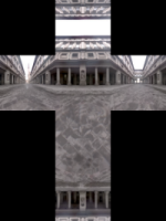
Subsections corresponding to each side of the cube are located in a horizontal cross pattern. Each subsection is one third of the image in height and one fourth in width.
Uses the flat 2‑D screen coordinates of the object (where 0,0 is the top left corner and 1,1 is the bottom right) to determine the texture uv. This is often used in conjunction with a background image to cause the colors on an object to match the background.
UV coordinates are generated from the actual position in world space of the object. This is useful for real-world size materials - especially 3‑D procedural textures.
UV coordinates are generated from a coordinate system specified by the world space location on the object and the side of an imaginary box pointed to by the object’s normal at that location. This is useful for real-world style materials, particularly 2‑D types like bitmaps, since the sides of objects will also be projected in a meaningful manner.
Uses the texture coordinates of that object on a specific mapping channel. By default, with a single mapping channel in use on an object, the texture coordinates will be generated from values found in Object Properties > Texture Mapping.
Texture previews will be modified by the mapping parameters. This can make it difficult to see the texture itself, if there is a high repeat, for example.
Displays the results of mapping a texture when that texture is not well displayed in the viewport. The texture is displayed temporarily as if it were the object color. This can be useful with advanced rendering engines where the viewport display does not support a particular rendering feature that can be textured (for example, reflectivity).
The graph control displays the color values at particular sections from the uv space of the texture. This can be useful when the color values are used to calculate parameters in non-color slots, such as bump, transparency.![]()
Shows the value of the red component of the texture.
Shows the value of the green component of the texture.
Shows the value of the blue component of the texture.
Shows the value of the alpha component of the texture.
Shows the combined luminance of the texture (calculated using the CIE standard method from the red, green and blue channels). This calculates non-color values such as transparency and bump.
Shows a section through the specified u parameter of the texture.
Shows a section through the specified v parameter of the texture.
Shows a section through the specified w parameter of the texture.
Allows the modification of the texture output with some common transformations.
Given a specific output color component (R, G, B), the clamp controls allow scaling and to zero the values above or below specified thresholds.
Turns component clamping on or off.
Scales the component values between the minimum and maximum values.
Sets the minimum value.
Sets the maximum value.
Transforms the image to its negative. For low dynamic range (LDR) images, this involves subtracting each component from 1.0. For HDR images, each component is replaced with its reciprocal.
Each color is replaced with a gray value based on the luminance.
Each color transforms by a given gamma. The effect is increased or decreased contrast.
Each color value is multiplied by a this amount. The effect is to increase or decrease brightness.
A simple adjustment to increase and decrease contrast and brightness.
Changes the image saturation where 1.0 is the original color saturation and 0.0 is fully gray.
Changes the hue value of each color by a given degree on the color wheel.
The 2D Checker texture is a planar texture that does provides a checker pattern in only two directions.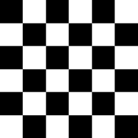
Causes child textures to be re-sized to fit into an individual checker.
The 3D Checker texture is a 3-D pattern. Sub textures can be set to each of the colors of the texture, and their u, v, and w can be re-mapped to the scale of the checker pattern.
Causes child textures to be re-sized to fit into an individual checker.
The Bitmap texture contains a simple bitmap image. You can also specify a transparent color to be used as an alpha channel in the case that no alpha channel is specified in the image.
Preview image
Size in pixels
Color depth
Image size
File size
Mirrors every other tile to allow easier edge matching on non-repeatable bitmaps.
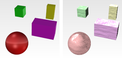
When multiple points on the surface are mapped to the same point in the texture the image can be "pixelated," displaying jagged lines and stair-stepped transitions between colors in the texture. Filtering smooths those transitions. In most cases the pixelation is smoothed out but if a very small texture is mapped to a very large surface the filtering tends to make things look blurry.
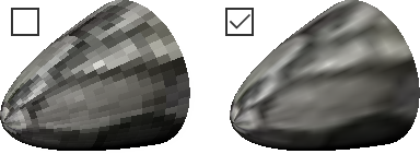
Enable filtering off (left) and on (right).
The path and name of the bitmap file.
 Browse for file
Open file browser.
Opens the image in your assigned image editor (Paint, PaintShop, or similar).
(Color selector)Specifies the color.
| Menu options | |
|---|---|
|
Color Picker |
Opens the Select Color dialog box. |
|
Eye Dropper |
Allows picking the color from anywhere on the screen. |
|
Copy |
Copies the color in the color swatch. |
|
Paste |
Pastes the color from one color swatch to another. |
The tolerance to be used to determine if the texture's color matches the transparency color.
Use the alpha channel stored in the image file.
The Blend texture is a simple color blending between two textures.
Blends Colors 1 and 2 using an amount of blend.
Blends Colors 1 and 2 using the luminance values of a texture.

The Cube Map texture takes six individual images arranged as separate cube map face images, and produces a linear cube map texture. This texture can then be converted into any other projection using the projection changer texture.
The texture to use at each face of the cube.
These buttons are always disabled. The image is always on.
The child texture to use.
These buttons are always disabled. The image always uses 100%.
The Dots texture generates a random dot pattern. Sub-textures can be set for the dot color and the background color.
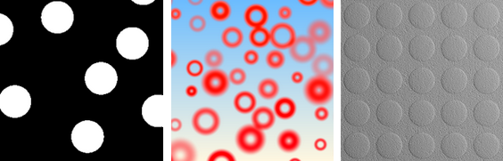
Default settings (left), customized settings (center), used a bump map (right).
Specifies the algorithm used to distribute the dots in space.
A low discrepancy sampler to generate dots that are randomly placed but uniformly distributed.
A perturbed grid pattern that is more memory efficient but tends to be less well distributed.
The approximate number of dots in the pattern.
Determines how far apart dots are generated. It operates like zooming in and out, but as you zoom in, more dots appear to keep the number of dots as close as possible to the #of dots value.
The Dot Style settings specify the way the dot merges into its background. These settings work well with bump mapping.
The fall-off type describes the shape of the dot when used as a bump map.
Generates flat dots that appear as simple discs.
Uses a linear method so that when used as a bump map, the bumps are conical with a very sharp center point.
Similar to Linear but uses a different method so that when used as a bump map, the bumps are more smooth and rounded.
Similar to Cubic but uses a different method so that when used as a bump map, the bumps have a domed appearance.
Specifies the radius of the dots.
Specifies a level of randomization for the radius.
Makes the dot into a ring with a variable size hole.
Specifies the size of the hole as a percentage of the radius.
Specifies the size of the hole as a percentage of the radius.
The Dot Appearance settings specify how the dot interacts with the background.
Specifies how the two dot colors are composited.
The dot blending functions are added together and the resulting value is used to interpolate between the background and foreground colors.
The maximum value for each color channel (R, G, B and A) is used.
Color channels are added.
Color channels are subtracted.
Color channels are multiplied.
Color channels are averaged.
This is the amount of the dot effect. When used as a color, it affects the brightness of the dot. When used as a bump map, it affects the depth of the bumps.
Specifies a level of randomization for the amplitude.
Normally the dots are colored according to the value of Color 2. This setting allows the color hue to randomly vary.
Specifies a level of randomization for the hue. This has no effect when the composition type is Standard.
Normally the dots are colored according to the value of Color 2. This setting allows the color saturation to randomly vary.
Specifies a level of randomization for the saturation. This has no effect when the composition type is Standard.
The Exposure texture takes high-dynamic-range information and converts it to a low-dynamic-range image using the same exposure algorithms used in the high-dynamic-range texture.
Add the high-dynamic range (HDR) texture whose exposure you want to control.
Changes the exposure of the HDR texture. It decides the part of the HDR dynamic range is mapped to the pixel range (0 to 255).
A scale factor that multiplies the final pixel color before it is displayed. The pixel color is then clamped to the range 0 to 255.
The fractal Brownian motion (fBm) texture is a standard computer graphics noise type where the noise is superimposed upon itself at different scales and amplitudes. So the closer you look, the more detailed the pattern is. A basic continuous noise function for bump maps based on Perlin noise. fBm is a variation on Perlin noise with either Fractal Sum synthesis. Textures can be set to the two colors in the noise function.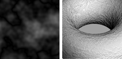
Similar effects are possible using the more complex but much more powerful Noise texture.
See: Wikipedia: Perlin noise.
The amplitude change between octaves.
The maximum number of super-impositions. This relates to the amount of detail in the noise.
A standard way of modifying the output of textures from linear to exponential.
The Gradient texture provides predefined gradient types along with custom curve support. Textures can be set to the two colors of the gradient.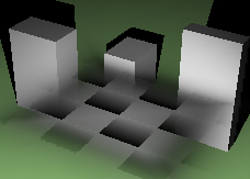
Gradient type
Specifies the way the colors combine.
|

Linear |

Box |

Radial |
|

Tartan |

Sweep |

Pong |
|

Spiral |
|
|
Opens the Custom Curve panel.
Drag points on the graph to reset the curves.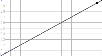
Adds edit points with handles to a curve.
Deletes edit points from a curve.
Selects all active curves.
![]() Red
Red
![]() Green
Green
![]() Blue
Blue
![]() Alpha
Alpha
Resets the thumbnail.
Resets the graph to the default settings.
Opens the panel as a free-standing control.
The Granite texture is a spotted 3-D texture. The granite procedure combines a randomly distributed spot component in a base component.
The overall size of the texture.
The size of the spots.
The amount of blending between the base color and the spot color.
The Grid texture uses a numbered grid bitmap as the texture.
The number of squares.
The size of the font used to number the grid squares.
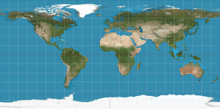
A High-Dynamic-Range (HDR) texture provides automatic conversion to a bitmap for non-HDR capable renderers. This allows the Rhino renderer and viewport display to show HDR environments. The HDR texture also provides projection conversion features. Most HDRi files come as light probe projection.
See: www.easyhdr.com/examples.
Image and file properties.
The path and name of the HDR.
Maps texture directly to background. Environment looks always the same no matter where the camera is looking.
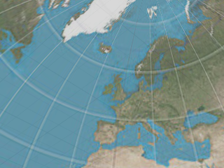
Also known as angular fish-eye projection or azimuthal equidistant projection. Elliptical subsection reaching each border of the texture is mapped onto the sphere.
See: Wikipedia: Azimuthal equidistant projection.
Also known as spherical projection. Horizontal line in the middle of the texture is mapped to the equator of the sphere.
See: Wikipedia: Equirectangular projection.
Subsections corresponding to each side of the cube are located side by side dividing the texture into six equal parts.
See: Wikipedia: Cube mapping.
Subsections corresponding to each side of the cube are located in a vertical cross pattern. Each subsection is one fourth of the image in height and one third in width.
Subsections corresponding to each side of the cube are located in a horizontal cross pattern. Each subsection is one third of the image in height and one fourth in width.
Elliptical subsection reaching each border of the texture is mapped onto the sphere. This projection is the result of taking a photo of a mirror sphere with an orthographic camera.
Like spherical projection but the entire texture is mapped onto the upper half of the sphere. The bottom border of the texture is stretched over the under side of the sphere.
Use the same projection as the input image.
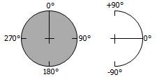
Modify the way the image is rotated in space during the projection conversion.
A simple linear multiplier on all values in the image. This can be used to brighten or dim the image in an HDR capable renderer.
Converts the image to a bitmap file.
Creates alternating slabs of base and vein components. 
The overall size of the texture
The fraction of the distance from one base stripe to the next. Values range from 0 for no Vein component to 1 for no base component.
Blurs the edges of the veins.
Adds noise to the texture.
The Mask texture creates a grayscale image from a specific component of an input texture. This is useful for creating textures suitable for non-color uses (like transparency, or bump). It is even more useful for calculating a mask from only a single component. It is most commonly used to extract the alpha channel from an input texture.
The texture to be used as input.
The texture component to be used as the output.
Calculates the output texture from the grayscale of the input image.
Calculates the output texture from the grayscale color made by using the red component for all components (R, R, R, 1.0).
Calculates the output texture from the grayscale color made by using the green component for all components (G, G, G, 1.0).
Calculates the output texture from the grayscale color made by using the blue component for all components (B, B, B, 1.0).
Calculates the output texture from the grayscale color made by using the alpha component for all components (A, A, A, 1.0).
The noise texture is a general purpose procedural texture for creating many types of coherent or partially coherent multi-octave noise. The texture is very useful as a building block for other procedural types, but can also be used on its own for non-repeating bump patterns or random variations in color.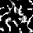
Many different types of noise for use in computer graphics have been developed. The noise texture provides several of them.
The classic noise developed by Ken Perlin in 1983.
See: Wikipedia: Perlin noise.
Creates a lattice of points which are assigned random values.
See: Wikipedia: Value noise.
The result of Perlin noise and Value noise added together.
A method for constructing an n-dimensional noise function comparable to Perlin noise but with a lower computational overhead.
See: Wikipedia: Simplex noise.
A noise method with accurate spectral control, easily mapped to a surface, and anisotropic filtering.
See: Procedural Noise using Sparse Gabor Convolution.
Similar to Value noise but with a different interpolation method.
A Hermite noise published by Greg Ward.
A coherent noise function developed by Robert McNeel & Associates.
Determines how the noise octaves are combined.
Results in a smooth noise function where there are no discontinuities.
Results in a non-smooth function where there are sudden discontinuities in the noise function.
Multi-layered noise is available by adding octaves. Noise octaves are additional noise waveforms layered onto the base wave at increasing frequencies and decreasing amplitude. Multi-layered noise can be used to simulate fractal-type effects such as ocean waves and landscape.
The frequency is multiplied by this number to reach the next octave.
Typically each octave is reduced in amplitude to create a fractal like pattern. This multiplier determines how much each octave is reduced by.
Sets the minimum and maximum values.
Scales the component values between the minimum and maximum values.
Transforms the image to its negative. For low dynamic range (LDR) images, this involves subtracting each component from 1.0. For HDR images, each component is replaced with its reciprocal.
A simple adjustment to increase and decrease contrast and brightness.
A simple Perlin marble texture implementation. 
See: Wikipedia: Perlin noise.
Sets the size of the marble pattern.
Sets the saturation level of Color 1.
Sets the saturation level of Color 2.
Sets the number of times the turbulence algorithm is applied. The higher the value, the more complicated the marble pattern.
Adds noise to the texture.
Blurs the edges of the veins.
The perturbing texture takes a source texture, and a texture that controls the perturbation of the source; generally a Noise or fBm texture although anything will work.
The source texture.
The texture that controls the perturbation of the source.
Adjusts the strength of the perturbing texture.
Creates a texture based on the appearance of the sky based on date, time, and location settings.
Uses the settings from the Sun panel.
Specifies the date. As you move the slider or enter a date in the edit box, the texture dynamically updates to reflect the change. The slider bar colors indicate the relative brightness of the sun at the specified date.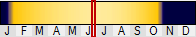
Specifies the time. As you move the slider or enter a time in the edit box, the texture dynamically updates to reflect the change. The slider bar colors indicate the relative brightness of the sun at the specified time.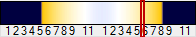
Sets the time and date from your computer’s clock.
Specifies the location and the Time Zone on Earth which is typically set from the closest city to the selected location.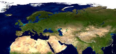
Sets the location from a city list.
Sets the time to the current system location.
Specifies a city in the city list.
Specifies the location's latitude.
Specifies the location's longitude.
Specifies the location's time zone.
Shows the sun in the texture.

The size of the sun in the rendered image.

The brightness of the sun.
The color of the sun's corona (halo around the sun).
The denser the atmosphere, the larger the Sun will appear because the atmospheric density acts as a magnifier.
How much the light particles spread out and how fast. This is similar to the way refraction works through transparent materials. As the sun approaches the horizon, the light scatters more and at a faster rate the lower it gets because you are looking through a thicker slice of the atmosphere, which causes the light to scatter more. Higher values cause the sun to appear more red.
Affects the results when the Sun is low on the horizon. Higher numbers cause thicker (smoggier) air. More particles “scatter” as the Sun approaches the horizon causing a greater effect (sunset, sun size, color distribution, etc...).
Attempts to model how wavelengths of light are diffused and refracted through our atmosphere. The settings represent the physical wavelengths of the primary colors. The default values are the physically correct values for our atmosphere (Earth). However, these values do not define the color of the sky, but rather how light interacts within the atmosphere due to its wavelengths using Rayleigh and Mie scattering models.
Multiplies the overall intensity. Brighter areas will become more intense than darker areas.
The projection changer texture converts a texture or image from one type of projection to another. The options available are the same as for the HDR image and cover most forms of texture projection. This can be very useful for conversion of environment maps.
See: Environment Editor, Projection.
See: Environment Editor, Projection.
Use the same projection type as the input image.
Modify the way the image is rotated in space during the projection conversion.
The Resample texture takes an input texture and divides it into pixels. The color of these pixels is determined by sampling the colors from the input texture. Fewer samples may result in noisy pixelation, especially on noisy input textures, but will be quicker.
It also has features for smooth interpolation between the pixel centers, and blurring controls. The re-sample texture is especially useful for creating blurred or pixelated versions of other textures, particularly procedural textures or HDR textures which cannot be easily blurred in an image editing package.
The input texture. Click to assign a new texture.
The number of pixels in the re-sampled texture in the u‑direction.
The number of pixels in the re-sampled texture in the v‑direction.
The minimum number of samples taken from the original image used to determine the color of the re-sampled pixel.
If the maximum is higher than the minimum, the input texture will be adaptively sampled up to the maximum number of samples.
The interpolate option causes the sample values taken from the grid to be linearly interpolated. For a grid of simple colors, clear this check box.
Texture colors will be generated using bi-linear interpolation between the colors at the nearest pixel centers. Causes the re-sampled texture to switch between pixelated and smooth.
Blurring causes the values of neighboring re-sampled pixels to be averaged with their near neighbors.
Turns blur on.
The re-sample texture supports four averaging types, each with its own characteristics.
Uses a simple and fast technique to sum and average neighboring pixels. This method can result in artifacts.
A fast averaging technique that reduces the edge artifacts.
A true Gaussian blurring technique that uses a bell-curve weighting to produce most accurate and artifact-free blur. This method can result in “over blurring” and can be slow.
A modification of the Gaussian curve that preserves details while keeping artifacts to a minimum. This method can be slow.
The radius determines how colors far from the original pixel contribute to the resulting pixel's color. A larger radius means more blurring. The radius is measured in texture units (1.0 means the entire width of the image). Values of around 0.1 - 0.2 work for significant blurred results.
Determines whether pixels at the left and right edges of the image can use color information from the opposite side of the image in the blurring results.
Determines whether pixels at the top and bottom edges of the image can use color information from the opposite side of the image in the blurring results.
Mirrors every other tile to allow easier edge matching on non-repeatable bitmaps.
When multiple points on the surface are mapped to the same point in the texture the image can be "pixelated," displaying jagged lines and stair-stepped transitions between colors in the texture. Filtering smooths those transitions. In most cases the pixelation is smoothed out but if a very small texture is mapped to a very large surface the filtering tends to make things look blurry.
Enable filtering off (left) and on (right).
The path and name of the bitmap file.
Browse for fileOpen file browser.
Opens the image in your assigned image editor (Paint, PaintShop, or similar).
The Single Color texture acts as a placeholder for either a color or a sub-node texture. It can be useful in situations where you want to instance colors across many materials or textures.
Click to use a texture.
Performs a basic randomized multi-sampling of the texture. This can help with moiré effects in sub-pixel ray sampling
The texture uses the wire color of the object being rendered instead of its own color. This means you can have a single Basic Material with this texture in the Color slot and each object using that material will be colored according to its Display Color attribute.
The Stucco texture generates a simple surface pattern useful for creating the effect of a stuccoed surface using bump mapping.
Controls the size of the bumps. Increasing this value appears to zoom in on the texture.
Controls the thickness of the bumpy areas. Higher values create more detail in the bumps.
Controls how pronounced the bumps are. Lower values make the texture more bumpy. Higher values smooth the texture out and show fewer bumps. A value of 1 makes the texture completely smooth.
The Texture Adjustment Texture provides a set of color and geometry adjustment settings that are applied to the child texture. The settings are much as the same as the adjustment section available for most textures.
The name of the image file.
Turns component clamping on or off.
Scales the component values between the minimum and maximum values.
Sets the minimum value.
Sets the maximum value.
Transforms the image to its negative. For low dynamic range (LDR) images, this involves subtracting each component from 1.0. For HDR images, each component is replaced with its reciprocal.
Each color is replaced with a gray value based on the luminance.
Each color transforms by a given gamma. The effect is increased or decreased contrast.
Each color value is multiplied by a this amount. The effect is to increase or decrease brightness.
A simple adjustment to increase and decrease contrast and brightness.
Changes the image saturation where 1.0 is the original color saturation and 0.0 is fully gray.
Changes the hue value of each color by a given degree on the color wheel.
Flips the image vertically.
Flips the image horizontally (as in mirror).
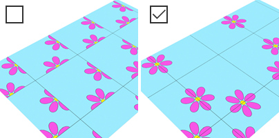
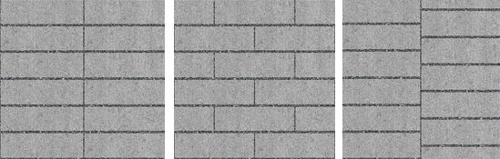
Tile textures are repeating patterns of color or texture or both.
Specifies the tile pattern.


Specifies the width of the joint color in each u,v, w direction.
The offset in tile space between each row or column of tiles (for each of the axes in u, v, and w). This is used to create brick-like patterns (where, for a simple stretcher bond, the u‑phase shift is 0.5).
The Turbulence texture creates a simplified partially coherent noise texture.
Similar effects are possible using the more complex but much more powerful Noise texture. Turbulence is a variation of Perlin noise Turbulence spectral synthesis.
See: Wikipedia: Perlin noise.
A measure of the contrast between noise levels.
The levels of fractal detail in the noise algorithm.
A simple adjustment to increase and decrease contrast and brightness.
The waves texture produces grayscale strips with a sine wave value curve in either a linear or radial pattern.
Produces linear waves (parallel lines).
Produces radial waves (concentric circles)
The steepness of the sine wave on the negative u side of the texture (1.0 is linear).
The steepness of the sine wave on the positive u side of the texture (1.0 is linear).
The distance in texture units between the waves.
Specifies the distance in simple texture units.
Specifies the distance by evaluating the luminance of another texture at that point.
The Wood texture consists of concentric cylinders of alternating Base and Ring components. The Wood procedure defines how the Base and Ring components combine.
The method used to create wood materials depends on how close it will be viewed.
If the viewpoint is not close to the wood, a solid color can take the place of wood without sacrificing image quality. This allows faster rendering.
The thickness of the wood grain. The thicker the grain, the more Color 2 affects the result and the less Color 1 does.
The amount of random variation in the grain. A value of zero makes the grain perfectly smooth. Higher values cause a more pronounced random variation in the grain.
Provides further random variation in the grain. This setting only has an effect when viewing the texture in 3‑D with WCS on and when Radial noise is greater than zero.
Controls the amount of blurring on the inner edge of the grain.
This controls the amount of blurring on the outer edge of the grain.
Render content (materials, environments, and textures) are stored in models. They can also be saved to files and shared across models. The Libraries panel displays the default content folder. Content can be dragged and dropped between Rhino sessions or between a Rhino window and a disk folder.
| Command-line options | |
|---|---|
|
ShowPanel |
Displays the Textures panel. |
|
Options |
Displays command-line options. AddDeleteRenameChangeDuplicateLoadFromFileSaveToFile |
| Toolbar | Menu |
|---|---|
|
|
|
The DownloadLibraryTextures command runs through the entire list of materials in the material library and downloads all of the required bitmap files from the Rhino server to the local computer. After that, any material can be used from the library without being online.
Opens the Environments panel.
Open or close the Materials panel.
Render the objects using the current renderer.
 Snapshots
The Snapshots command saves and restores Named Views, Named Positions, Layer States, as well as rendering settings, object settings including locked/hidden state, display mode, material, position, light settings, curve piping, displacement, edge softening, shutlining, and thickness.
Rhinoceros 6 © 2010-2020 Robert McNeel & Associates. 11-Nov-2020
