QuadRemesh
|
Toolbar |
Menu |
|---|---|
|
|
SubD / Mesh Edit Tools > Quad Remesh |
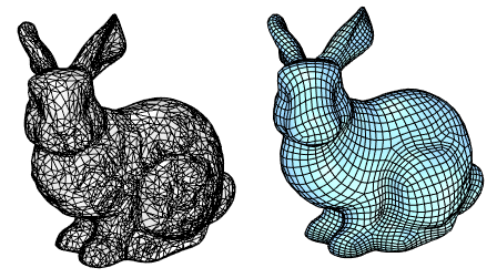
The QuadRemesh command quickly creates a quad mesh with optimized topology from existing surfaces, meshes, or SubDs. It uses a unique algorithm to generate manageable polygon meshes, ideal for rendering, animation, CFD, FEA, and reverse-engineering.
Options
 Target Edge Length
Sets the approximate edge length of the output mesh.
- This setting is scale dependent. The resulting face count increases with object scale.
- Re-meshing would fail if the target edge length is set too large for the object size.
 Target Quad Count
Sets the approximate face count of the output mesh as a goal for the algorithm.
- This setting is scale independent. An input object in different scales produces a similar face count.
Adaptive Size (0-100)
Set 0 to get a minimal number of quads and uniform sizes. A value above 30 will diminish your control of getting a smaller number of quads. Higher values result in smaller quads in high curvature areas. Set 100 to keep more details.
0 |
100 |
|
Face shape |
As square as possible |
Varies in width and height |
Face size |
Similar |
Varies |
Face density |
Uniform |
Higher at details |
Fit to original shape |
Less |
More |
Respect to target face count |
More |
Less |
Risk |
Topology irregularities |
More faces |
 Adaptive Quad Count
Use Surface Edges (Polysurface/Extrusion only)
Specifies if meshes edges will be created along the sub-face boundaries on the input object.
Off
Ignores sub-face boundaries.
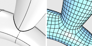
Smart
Retains sub-face boundaries except for the ones being determined as meaningless by the algorithm. This is usually the best choice.
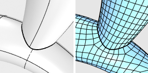
Strict
Retains all sub-face boundaries.
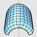
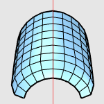
Symmetry Axis:  X Y Z
X Y Z
Select to perform symmetrical re-meshing across the X, Y, or Z central plane of the object's bounding box. Multiple axes can be selected. It only makes sense for symmetrical objects and when the correct symmetrical plane is selected.
|
|
|
|
Disabled
|
Enabled
|
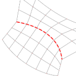
Guide Curves
The quad re-meshing algorithm will try to place edge loops or edge rings along guide curves. Guide Curves can be used to define more details, or simply influence the direction of quad re-meshing in a region. Guide curves must be projected onto the input object to have an effect. Click to select guide curves.
Curve Influence
These options control how guide curves affect the final quad mesh.
None
No effect on the result.
Approximate
Adjusts the general direction of the quads by influencing their natural flow. The guide curves have a weak effect on the result.
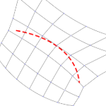
Create Edge Ring
Orients the crossing edges perpendicular to the guide curves. The guide curves have a stronger effect on the result, but edge rings may not follow guide curves exactly.
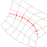
Create Edge Loop
Places edge loops along guide curves. The guide curves have the strongest effect on the result.
Detect Hard Edges
Uses a 30-degree break angle threshold to divide the quad mesh with hard edges (creased edges). If the break angle between two adjacent faces is larger than 30 degrees, a hard edge loop will be added.
Turn this option off if...
-
You do not want hard edges on the quad meshes.
-
The input mesh is disorganized to avoid adding unintended hard edges.
Convert to SubD
Converts the resulting quad mesh into a SubD that results in a smoothed curved surface. Hard edges will be retained when possible.
This option is equivalent to the ToSubD command.
SubD Creases
Converts the creased edges added by the Detect Hard Edges option on the quad mesh into creased edges on the output SubD.
This option is equivalent to the MeshCreases option of the ToSubD command.
SubD corners
Converts the corner vertices on the quad mesh into SubD corner vertices.
This option is equivalent to the MeshCorners option of the ToSubD command.
Interpolate SubD
On - The quad mesh vertices are used as SubD vertices. The SubD will lie on the quad mesh. This is usually used for reverse engineering
Off - The quad mesh vertices are used as SubD control polygon points. The result will be slightly smaller or larger than the input shape.
This option is equivalent to the UseMesh option of the ToSubD command.
Preview
Previews the result of quad re-meshing. The preview will update when the settings are changed.
Preview calculates the average edge length and face count near the bottom of the dialog box.
Hide Input Objects
If the input object has dense wireframes, the preview will not be visible. Enable this option to see the preview.
Delete Input Objects
Delete the input objects when re-meshing is done.