This tutorial demonstrates using solid primitives and simple transforms.
You will learn how to:
| ● | Enter coordinates to place points exactly. |
| ● | Draw a free-form curve and polygon. |
| ● | Create a pipe along a curve. |
| ● | Use a polar array to copy objects in a circular pattern. |
| ● | Extrude a curve to create a surface. |
| ● | Use planar mode.
|
When you pick a point with the mouse, the point lies on the construction plane of the active viewport unless you use a modeling aid such as object snap or elevator mode. When Rhino prompts for a point, you can enter x-, y-, and z-coordinates instead of picking a point. Each viewport has its own construction plane on which its x- and y-coordinates lie. The z‑coordinate for the active viewport is perpendicular to the x‑y plane.
The grid is a visual representation of the construction plane. The intersection of the dark red and green lines shows the location of the origin point (x=0, y=0, z=0) of the coordinate system.
This exercise uses x-, y-, and z-coordinates to accurately place points. When you are to type coordinates, type them just as they are shown in the manual. The format is x,y,z. For example, type 1,1,4. You must type the commas. This sets the point at x=1, y=1, and z=4 in the active viewport.
Whenever you type points, look in all viewports at where the point is placed so you can start getting an idea of how coordinate entry works.
![]() Start the model
Start the model
| 1. | Begin a New model. |
| 2. | In the Open Template File dialog box, select Small Objects - Centimeters.3dm, and click Open. |
![]() Draw an ellipsoid
Draw an ellipsoid
| 1. | Turn on Ortho. |
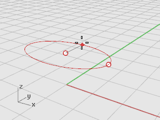
| 2. | On the Solid menu, click Ellipsoid > From Center. |
| 3. | With the Top viewport active, at the Ellipsoid center… prompt, type 0,0,11, and press Enter. This places the center point of the ellipsoid at x=0, y=0, and z=11. Look at the point in the Perspective viewport. |
| 4. | At the End of first axis… prompt, type 15, and press Enter. |
| 5. | Move the cursor to the right to show the direction and click.
|
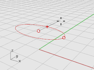
| 6. | At the End of second axis prompt, type 8, and press Enter. |
| 7. | Move the cursor up to show the direction and click. This sets the width of the ellipsoid.
|
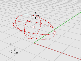
| 8. | At the End of third axis prompt, type 9, and press Enter. You now have an egg shape that has different dimensions in all three directions.
|
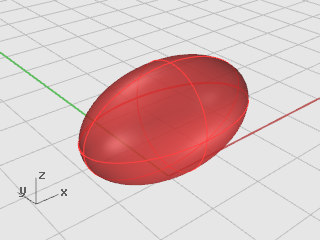
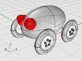
| 9. | Rotate the perspective viewport so you are looking along the x-axis as illustrated. Turn on Shaded display mode in the Perspective viewport.
|
The axles and wheel hubs are cylinders. The axles are long, thin cylinders, and the wheel hubs are short, fat cylinders. You are going to make one axle and one complete wheel. You will then mirror the complete wheel to the other side. You can then either mirror or copy the complete axle and wheel set to the front of the toy.
![]() Create the axle
Create the axle
| 1. | On the Solid menu, click Cylinder. |
| 2. | With the Front viewport active, at the Base of cylinder… prompt, for the location of the cylinder's center, type 9,6.5,10, and press Enter.
|
| 3. | At the Radius… prompt, type .5, and press Enter. |
| 4. | At the End of cylinder prompt, type -20, and press Enter.
|
![]() Create a wheel hub
Create a wheel hub
| 1. | On the Solid menu, click Cylinder. |
| 2. | With the Front viewport active, at the Base of cylinder… prompt, type 9,6.5,10, and press Enter.
|
| 3. | At the Radius… prompt, type 4, and press Enter. |
| 4. | At the End of cylinder prompt, type 2, and press Enter.
|
You will make the lug nuts by extruding a hexagonal polygon curve.
![]() Create a hexagon
Create a hexagon
| 1. | On the Curve menu, click Polygon > Center, Radius. |
| 2. | At the Center of inscribed polygon ( NumSides=4… ) prompt, type 6, and press Enter. |
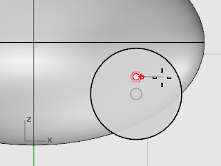
| 3. | In the Front viewport, at the Center of inscribed polygon… prompt, type 9,8,12, and press Enter. This will place the polygon right on the surface of the wheel hub. |
| 4. | At the Corner of polygon… prompt, type .5, and press Enter. |
| 5. | In the Front viewport drag the cursor as illustrated, and click to position the hexagon.
|
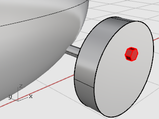
![]() Make a solid from the polygon
Make a solid from the polygon
| 1. | In any viewport, select the hexagon you just created. |
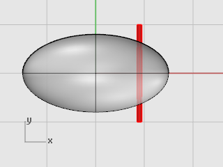
| 2. | On the Solid menu, click Extrude Planar Curve > Straight. |
| 3. | At the Extrusion distance prompt, notice the command-line options. Set the options as follows: Direction - use default BothSides=No Solid=Yes DeleteInput=Yes ToBoundary - use default SplitAtTangents=No SetBasePoint - use default If the option is not set as listed above, click the option to change it. |
| 4. | At the Extrusion Distance… prompt, type -.5 (Notice the negative number. If you type a positive number at this point, the nuts will be buried in the wheel hub. You want them to stick out.), and press Enter.
|
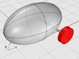
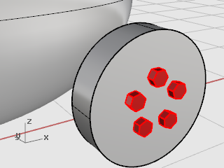
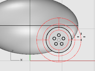
To create the lug nuts on the first wheel, you are going to use a polar (circular) array. An array is a set of copies of an object. You control how the copies are made. A polar array copies the objects around a central point. The objects are rotated as they are copied.
![]() Array the nuts around the center
Array the nuts around the center
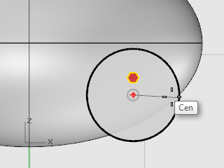
| 1. | Select the lug nut. |
| 2. | On the Transform menu, click Array > Polar. |
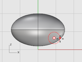
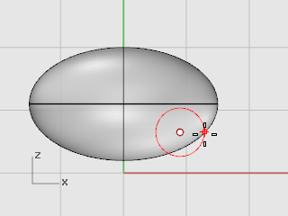
| 3. | With the Front viewport active, at the Center of polar array prompt, use the Cen object snap to snap to the center of the hub.
|
| 4. | At the Number of elements… prompt, type 5, and press Enter. |
| 5. | At the Angle to fill <360> prompt, press Enter. |
| 6. | At the Press Enter to accept prompt, check the preview, and press Enter.
|
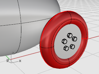
The tires are a solid form called a torus, which looks like a donut. When you are drawing a torus, the first radius is the radius of a circle around which the “tube” is drawn. The second radius is the radius of the tube itself.
To draw the tires, you will draw the center of the torus tube a bit larger than the diameter of the wheel hub. The tube itself is slightly larger than the hub. This makes it dip into the hub.
![]() Create a torus for the tires
Create a torus for the tires
| 1. | On the Solid menu, click Torus. |
| 2. | In the Front viewport, at the Center of torus… prompt, type 9,6.5,11, and press Enter. This places the center of the torus at the same point as the center of the wheel hub.
|
| 3. | At the Radius… prompt, type 5, and press Enter. This makes the radius of the torus tube one unit bigger than the wheel hub. |
| 4. | At the Second radius… prompt, type 1.5, and press Enter. This makes the inner dimension of the torus tube .5 units smaller than the wheel hub.
|
Now that you have a whole wheel created, you can use the Mirror command to create the other three.
![]() Mirror the wheel to the other side
Mirror the wheel to the other side
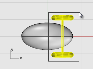
| 1. | In the Top viewport, use a window to select the wheel as illustrated. |
| 2. | On the Transform menu, click Mirror. |
| 3. | At the Start of mirror plane… prompt, type 0,0,0, and press Enter.
|
| 4. | At the End of mirror plane… prompt, with Ortho on, drag to the right in the Top viewport as illustrated and click.
|
![]() Mirror the front wheels and axle
Mirror the front wheels and axle
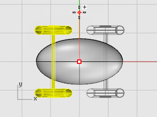
| 1. | In the Top viewport, use a window to select the wheels and axle as illustrated. |
| 2. | On the Transform menu, click Mirror. |
| 3. | At the Start of mirror plane… prompt, type 0,0,0, and press Enter.
|
| 4. | At the End of mirror plane… prompt, with Ortho on, drag down in the Top viewport as illustrated and click.
|
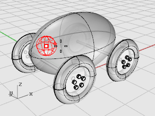
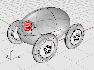
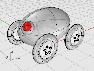
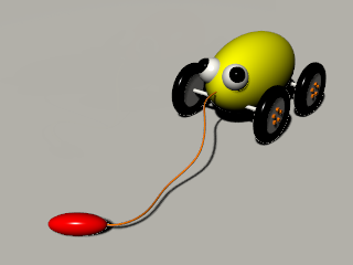
You are going to draw a sphere for an eye and a smaller sphere for the pupil.
![]() Create an eye using a sphere
Create an eye using a sphere
| 1. | On the Solid menu, click Sphere > Center, Radius. |
| 2. | At the Center of sphere… prompt, in the Top viewport, type -12,-3,14, and press Enter.
|
| 3. | At the Radius… prompt, type 3 and press Enter.
|
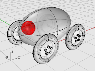
![]() Create the eye pupil
Create the eye pupil
| 1. | Repeat the Sphere command. |
| 2. | At the Center of sphere… prompt, in the Top viewport, type -13,-4,15, and press Enter.
|
| 3. | At the Radius… prompt, type 2 and press Enter.
|
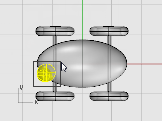
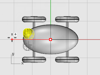
![]() Mirror the eye
Mirror the eye
| 1. | In the Top viewport, use a window to select the eye as illustrated. |
| 2. | On the Transform menu, click Mirror.
|
| 3. | At the Start of mirror plane… prompt, type 0 (this is a shortcut for typing 0,0,0), and press Enter. |
| 4. | At the End of mirror plane… prompt, with Ortho on, drag to the left in the Top viewport as illustrated and click.
|
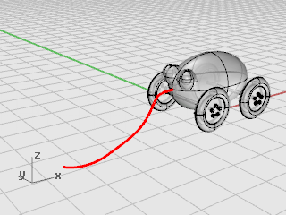
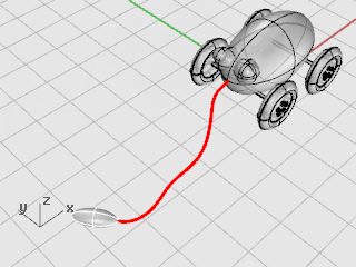
To make the cord, you are going to draw a freehand curve using elevator and planar mode. When the curve is complete, use the Pipe command to make it a thick solid.
Set up the view
| 1. | Zoom out in all the viewports; you are going to need some space to work. |
| 2. | On the status bar, turn Planar mode on, and turn Ortho off. |
| 3. | In the Osnap control, click Disable to turn off all object snaps. |
![]() Create the pull cord at the front of the toy
Create the pull cord at the front of the toy
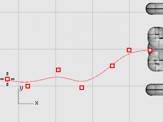
| 1. | On the Curve menu, click Free-form > Control Points. |
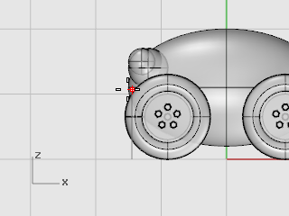
| 2. | At the Start of curve… prompt, in the Top viewport, hold the Ctrl key to activate elevator mode and click near the front end of the body ellipsoid. |
| 3. | Move the cursor to the Front viewport, drag the marker near the end of the ellipsoid, and click.
|
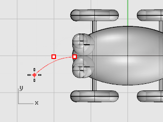
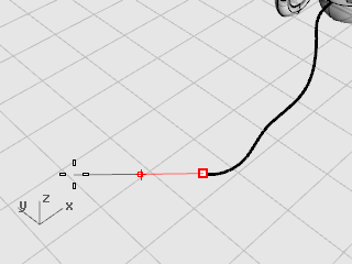
| 4. | At the Next point… prompt, click to the left of the ellipsoid in the Top viewport.
Planar mode keeps successive points at the same construction plane elevation. Planar mode can be overridden with elevator mode or object snaps. Watch the curve in the Top and Front viewports. |
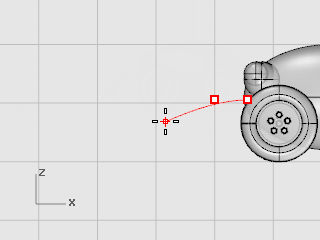
| 5. | At the Next point… prompt, use elevator mode to add another point in the Top viewport.
|
| 6. | At the Next point… prompts, turn off Planar mode and click several more points in the Top viewport to create a curved line.
Notice that the points are projected to the Top construction plane.
|
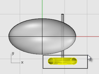
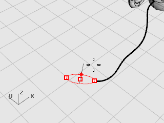
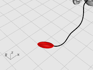
![]() Make the cord handle
Make the cord handle
| 1. | Draw an Ellipsoid with the Diameter option to represent a handle at the end of the curve. |
| 2. | At the Start of first axis prompt, use the End object snap to pick the end of the cord curve. |
| 3. | At the End of first axis prompt, type 10 to set the length, and press Enter. |
| 4. | Drag the direction so it lines up with the cord curve and click to set the direction. This does not have to be very accurate.
|
| 5. | At the End of second axis prompt, type 4, press Enter, and drag to set the direction.
|
| 6. | At the End of third axis prompt, type 2, and press Enter.
|
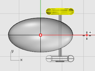
![]() Thicken the curve with a pipe
Thicken the curve with a pipe
| 1. | Select the curve you just made at the front of the pull toy. |
| 2. | On the Solid menu, click Pipe. |
| 3. | At the Start radius… prompt, type .2, and press Enter. |
| 4. | At the End radius… prompt, press Enter. |
| 5. | At the Point for next radius prompt, press Enter. The pipe will be the same diameter for the full length of the curve.
|