DraftAngleAnalysis
| Toolbar | Menu |
|---|---|
|
|
Analyze Surface > Draft Angle Analysis |
The DraftAngleAnalysis command visually evaluates surface draft-angle using false-color analysis.
Draft angle is often used to design injection-molded parts that must eject from molds.

Input
- Surface, Polysurface, Extrusion, Mesh, SubD
Steps
- Select objects.
- In the Draft Angle dialog box, set the angle for the color display.
- Set the pulling direction.
- Adjust the density of the mesh if the level of detail is not fine enough.
Draft Angle Analysis options
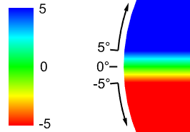
- If you set the upper and lower values to the same, all portions of the object that exceed the draft angle will be red.

Set direction by
Select an option that defines the pulling direction.
World Z
Uses the +Z of the world axes.

CPlane Z
Uses the +Z of the CPlane in the current viewport.
- Click to update the direction based on the current viewport.
View based
Uses the inverted view direction (target towards camera) of the selected viewport.
- Click to update the direction based on the current viewport.

Two points
Uses the direction defined by picking two points.
- Click and pick two points in the viewport.

Curve or edge
Uses the tangent direction at the start point of the selected curve or edge.
- Click and select a curve or an edge in the viewport.

<Named CPlane>
Uses the +Z of the selected Named CPlane.
 Show edges and isocurves
Displays edges or isocurves on the analyzed objects.
Add max. draft curve
Creates a curve along the line where the draft angle is equal to the upper value.
Add mid draft curve
Creates a curve along the line where the draft angle is 0.
Add min. draft curve
Creates a curve along the line where the draft angle is equal to the lower value.
Click to create curves based on the state of the draft curve checkboxes above.

Open Analysis Mesh Options to change analysis mesh density. Increasing mesh density improves the analyzing accuracy.
Select more objects to analyze.
Remove selected objects from the analysis.
| Toolbar | Menu |
|---|---|
|
|
|

The DraftAngleAnalysisOff command turns off draft angle analysis.
| Toolbar | Menu |
|---|---|
|
|
|
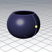
The DraftAnglePoint command places a point object at a surface's draft angle break location.
Draft angle is often used to design injection-molded parts that must eject from molds.
Tip
- One way to find locations on the surface close to the desired draft angle is to turn on DraftAngleAnlaysis. Set the upper and lower limits to bracket the desired angle closely. For example, if the angle is 5, set the limits to 4.9 and 5.1.
- Use a dense analysis mesh. Points can then be picked along the strip dividing the red from the blue parts of the surface. The points will be on the break line.
Command-line options
Angle
The angle in world coordinates of a line tangent to the surface at the draft angle point.
PullDirection
The direction of the part ejection in world coordinates.
Edge
Restricts the point placement to an edge.