BlendSrf
| Toolbar | Menu |
|---|---|
|
|
Surface Blend Surface |
The BlendSrf command creates a transitional surface between two surface, polysurface, or extrusion edges.
Steps
-
Select the first edge.
Use the ChainEdges option to select an edge chain.
-
Select the second edge, or another edge chain.
-
Adjust the blend settings or handle control points, click .
| Command-line option | |
|---|---|
|
ChainEdges |
Selects connected edges that will be considered a single edge. |
|
Edit |
Changes the blend settings and handles for the blend surface created with History. History locking temporarily turns off when editing a blend surface with History. |
| Keys for control | |
|
|
|
|
Shift |
By default the shape curves are separately edited at each end, Hold Shift to retain symmetry. With symmetry, point editing is mirrored to the other end of the curve. |
|
Alt |
Hold Alt while dragging the handles to change the angle between the shape curve and the surface edge.
|
To adjust seams
-
Select each seam point and move it along the curve to line up all curve seams.
-
Use the Flip option to make all seam arrows point to the same side.
-
Press Enter to continue.
Adjust seam options (Closed curves only)
Flip
Reverses the curve direction.
Automatic
Attempts to align the seam points and directions without intervention.
Natural
Moves the seam points to the way they were at the beginning of the command.
Adjust Surface Blend options
 Lock
Lock
Maintains the relationship between the two curve ends.
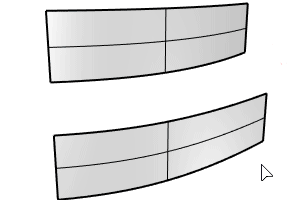
Slider
Determines the distance of influence the surface has on the edge curve.
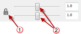
Sliders (2) control each surface end.
Lock sliders icon (1), surface end bulge controls (2).
Continuity options
Sets the continuity for each surface end.
Adds additional curve profile shapes to increase control over the blend surface shape. This is especially important if the input shapes are complex and you want to control the shape in more locations.
- Click a location on each surface edge to add another shape curve.
When you snap to a point and add a shape, the command automatically creates a shape that connects to the corresponding point on the other side, which attempts to keep the blend simple.
Removes curve profile shapes.
Click to automatically add shapes that make the blend surface isocurves less twisted.
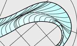
<Angle>
The angle threshold used to evaluate where more shapes are required.
If the angle between the isocurve direction (1) and rail tangent direction (2) is less than the angle threshold, a shape will be added. When a shape is added, the surface is rebuilt and then re-evaluated.

 Interior shapes
Turns on or off including all of the shapes at Greville points for simple blends. The use of interior shapes takes the entire surface edge selection taken into account for continuity.
The Interior shapes and Refine checkboxes cannot be enabled at the same time.
 Refine
Avoids creating a simpler blend surface when it is possible to do. More isocurves will be added to the blend surface.
Planar sections
Forces all shape curves to be planar and parallel to the specified direction.
Same height
If the gaps between the surfaces vary, this option maintains the height of the shape curves throughout the blend.
Note
- If you try to create a blend between a surface and a hole in another surface that is exactly the same size as the surface, Rhino will be forced to make the blend surface dip in quite a bit so it is smooth to both surfaces.
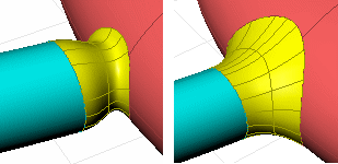
Hole the same size as surface (left). Hole larger than surface (right). - If the edges of two surfaces you are trying to blend share a corner intersection, the BlendSrf command will select all the contiguous edges as one. To choose the second edge separately, press Enter after choosing the first edge, then choose the edge of the second surface.
- Sometimes some holes appear in rendering between blend surfaces and their original surfaces appear in rendering. This is because the rendering was done with polygon mesh approximations of the true surfaces, so the meshes are not matching up exactly.
- Use the Join command to join them together into one object so the rendering and meshing won't have any cracks in it and will match up exactly.
Tips
- Always blend from the largest radius to the smallest radius across a model.
- Remove any edges you can prior to blending with MergeAllCoplanarFaces or by way of surfacing in a simpler manner. Fewer intersected edges = Fewer problems as the blend rolls along any edges and tries to trim and join with the adjacent surfaces.
- Make sure there is enough room for the blend surface to trim and join with adjacent surfaces. The angle relationships between surfaces, sharpness of the bend in the edge around corners, and blend type all play a part in any particular case.
See also
Zebra
Visually evaluate surface smoothness and continuity using a stripe map.