Texture Mapping
|
Toolbar |
Menu |
Panel Gear Menu |
Shortcut |
|---|---|---|---|
|
|
Edit Object Properties Panels Properties |
Properties |
F3 |
Texture mapping properties manage texture map projections for selected surfaces, polysurfaces, and meshes.
Mapping is a process of defining how to represent a 2‑D image on a 3‑D model. Mapping transforms a 2‑D source image into an image buffer called a texture.
A texture can be applied to the surface of a 3‑D model to add color, texture, or other surface detail like glossiness, reflectivity, or transparency.
The problem of how to represent the texture in 3-D rendering can be overcome by means of uv‑mapping. U and V are the coordinates of the texture corresponding to X and Y. Think of u as one direction on a piece of graph paper (side to side). Think of v as the other direction (up and down).
Any time an image is applied in a material and then applied that material to a model, uv‑texture mapping is used.
Mapping channel
A mapping channel holds a set of texture-mapping parameters. Each mapping channel is identified by a number. An object can have any number of channels and therefore can hold any number of texture mapping types.
Textures in materials can be assigned a channel number. When the textures are applied to an object, the texture is applied using the matching channel number on the object. Texture channels default to channel 1.
If an object has no applied texture mapping, surface mapping is used to map the texture.
![]() Properties Panel
Properties Panel
Environment map, Screen, and WCS* mapping styles set in the material texture override texture mapping properties. You will see this message when it happens.

Click the blue text string below the message to change the material texture to use a mapping channel. Texture mapping properties will then take over the control.
 Unwrap
Unwraps the texture for editing.
See: Unwrap.
 Custom Mapping
Add a custom mapping channel.
 Surface Mapping
Add a surface mapping channel. The default texture mapping method for surfaces and polysurfaces is set by the control point structure of the surfaces.
 Planar Mapping
Add a planar mapping channel.
 Box Mapping
Add a box mapping channel.
 Spherical Mapping
Add a spherical mapping channel.
 Cylindrical Mapping
Add a cylindrical mapping channel.
 Delete Mapping
Delete a mapping channel.
 Match Mapping
Match the mapping to another object's mapping.
 Edit Channel (Use multiple mapping channels only)
Allows changing the channel number.
 Show Mapping
Display the mapping widgets for the object.
 Hide Mapping
Hide the mapping widgets for all objects.
 UVEditor
Opens the UV Editor.
See: UVEditor.
Use multiple mapping channels
Allows more than one mapping channel for a single object. The channel numbers can be changed by using the edit channel icon. These mapping channel numbers are used in the texture map settings for an objects material to control which mapping channel is used for that texture.
Channels
#
The mapping channel number.
Type
The mapping type.
Name
The name of the mapping.
Name
The name of the mapping.
See: Naming conventions in Rhino
Projection
Closest point
Ray
Type
The mapping type.
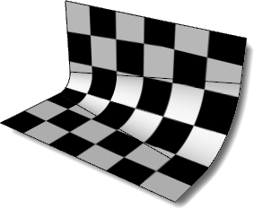
Surface
Surface mapping stretches the texture over the object.
In this example, a variable radius fillet connects two planar surfaces and all are joined into one polysurface. The default surface mapping method uses the control point structure of each individual surface to orient the checkered texture map applied to the material. Notice how the checker texture does not match across seams in the polysurface.
See: ApplySurfaceMapping.
Planar
Planar mapping projects a 2-D plane onto the side of an object.
See: ApplyPlanarMapping.
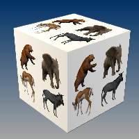
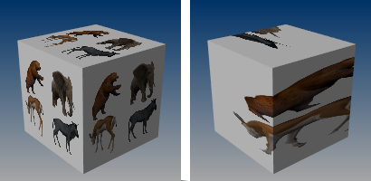
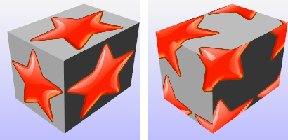
Box
Box mapping projects a 3-D box onto the sides and top of an object.
See: ApplyBoxMapping.
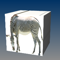
Box (sides only)
Box mapping sides of an object only, does not cap the mapping to the top and bottom surfaces.
See: ApplyBoxMapping.
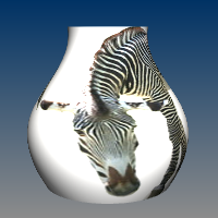
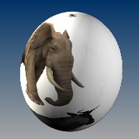
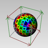
Spherical
Spherical mapping wraps the object around a sphere. The top edge of the texture shrinks into the top pole and the bottom edge into the bottom pole.
See: ApplySphericalMapping.
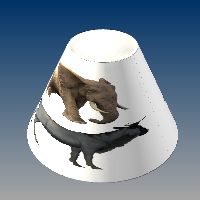
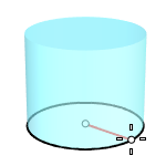
Cylindrical
Cylindrical mapping an image around an object like a cylinder the left and right edge will join each other.
See: ApplyCylindricalMapping.
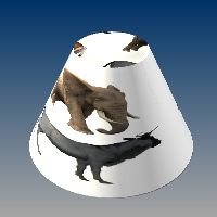
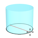
Capped cylindrical
Capped cylindrical mapping also maps the image to the top and bottom of the objects.
See: ApplyCylindricalMapping.
OCS frame
The OCS frame type lines up textures with the object rather than the world coordinates when textures use WCS/OCS or WCS/OCS (Box style) mappings. This mapping type can only be added by the ApplyOcsMapping command.
Custom
Add a custom mapping channel.
Custom surface objects control the mapping of textures over any other object.
This process is limited to single surfaces as the surface control point structure is used to control the applied mapping. Here, the surface in front of the polysurface was selected when prompted for the custom object in the command line.
Custom Mapping Steps
- Select the custom mapping object.
Projection
When a mesh is texture mapped, some UV(W) values have to be assigned to each vertex from another object – either a primitive like a sphere or a custom object like another mesh or surface.
Each mesh vertex is assigned a parameter from the other object’s UV space.
Closest point
Finds the closest point on the primitive from the point on the mesh.
Ray
Ray draws a line from the mesh along its normal until it hits the primitive.
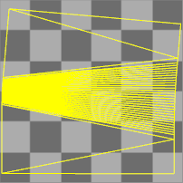
Texture space
Single texture space (left), divided texture space (right).
Single
Specifies that the texture will be mapped individually over each independent space.
Divided
Specifies that distinct regions of the texture will be used for each space, matching parts of the mapped object to the six independent texture spaces.
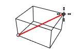
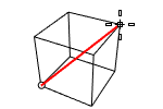
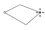
XYZ position
Sets the center point of the texture mapping widget in world coordinates.
Default position (left), position moved to a different location (right).
 Pick button
Click to pick a location on the screen.
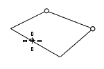
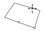
XYZ rotation
Sets the rotation of the texture in world space.
Default rotation (left), x rotation 60 degrees (right).
XYZ size
The texture size.
Lock
When the mapping widget has been re-sized with unequal scaling, the scaling is locked to the specified aspect ratio.
1,1,1
Sets the texture size to 1 in all three directions.
x=y=z
Sets the texture size to be equal in all three directions.
>[ ]<
Fits the texture to the object as established by the original mapping.
Size to image aspect
Sets the size to the aspect ratio of the image.
UVW offset
The amount the texture is offset from the origin of the UVW texture space.
UVW repeat
The number of times the texture repeats across the object in UVW texture space.
Lock
When Lock is checked, the repeat values for u, v, and w change together so that they stay in the same relationship to each other.
When Lock is unchecked, the repeat values can be changed independently of each other.
Example:
If Lock is off, and you enter 1, 2, 3 in the UVW boxes, you will get one repeat in u, two repeats in v, and three repeats in w.
If you then check Lock, and change the 1 to a 2, the values will change to 2, 4, 6. If you then change the 6 to 60, you will get 20, 40, 60.
UVW rotation
The rotation angle of the texture over the object in UVW texture space.
Related commands
| Toolbar | Menu |
|---|---|
|
|
|

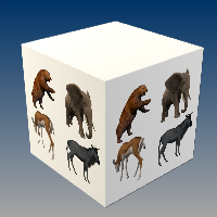
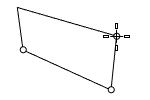
The ApplyBoxMapping command adds a box texture mapping channel to an object and sets the mapping type to box.
Object with box mapping widget on.
Steps
-
Select objects, and press Enter.
-
Draw the mapping widget box.
-
Select the coordinate system.
-
Specify if the box will be capped.
-
Enter a mapping channel number, or press Enter to accept the default value.
Command-line options
BoundingBox
Uses the object bounding box to determine the location and size of the mapping widget.
CPlane
Uses Construction plane coordinates for the bounding box.
World
Uses World coordinates for the bounding box.
Diagonal
Creates a box from the diagonal corners. If you pick the two corners on the CPlane, the command prompts for picking the height.
(Default)
Draws the rectangle using two opposite corners.
3Point
Draws the rectangle using two adjacent corner locations and a location on the opposite side.
EdgeMidpoint
Draws the rectangle from the midpoint of the first edge, an end of the edge, and a location on the opposite side.
Vertical
Draws the rectangle perpendicular to the construction plane.
Center
Draws the rectangle from the center point and a corner.
Capped
Applies the mapping to all six sides of the box.
| Toolbar | Menu |
|---|---|
|
|
|
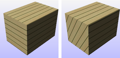
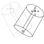
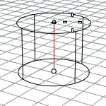
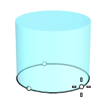
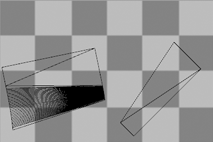
The ApplyCylindricalMapping command adds a texture mapping channel to an object and sets the mapping type to cylindrical.
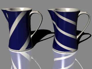
Surface mapping (left), cylindrical mapping (right).
Steps
-
Select objects, and press Enter.
-
Draw the mapping widget cylinder.
-
Select the coordinate system.
-
Specify if the cylinder will be capped.
-
Enter a mapping channel number, or press Enter to accept the default value.
Command-line options
BoundingBox
Uses the object bounding box to determine the location and size of the mapping widget.
CPlane
Uses Construction plane coordinates for the bounding box.
World
Uses World coordinates for the bounding box.
DirectionConstraint
Direction constraints restrict the direction of the cylinder.
None
Pick or type a number to set the height.
- Use elevator mode, object snaps, or other modeling aids to help picking a location.
- The cursor location defines the positive direction when you type a number to set the height.
Vertical
Creates a cylinder perpendicular to the construction plane.
- The CPlane +Z direction defines the positive direction when you type a number to set the height.
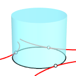
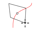
AroundCurve
Draws the base circle perpendicular to the picked point on a curve. The center line of the cylinder will be tangent to the curve.
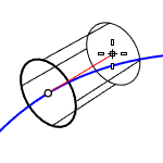
- The curve direction defines the positive direction when you type a number to set the height.
Radius
Draws the base circle by picking the center point and a radius point.
2Point
Draws the base circle from two opposite points.
3Point
Draws the base circle through three points.
Tangent
Draws the base circle tangent to one, two, or three curves.
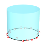
FitPoints
Draws the base circle by fitting to selected points, control points, or mesh vertices.
Capped
Applies the mapping to the top and bottom of the cylinder.
| Toolbar | Menu |
|---|---|
|
|
|
The ApplyCustomMapping command adds a custom texture mapping channel to an object.
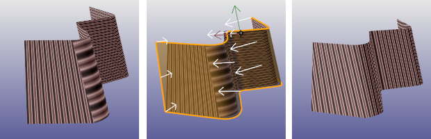
No mapping or surface mapping (left), custom mapping object (center), result of custom mapping.
A specified mesh or NURBS surface or polysurface acts as the mapping for the selected objects. The mapping object is preserved in the mapping table so deleting the mapping object does not affect the mapping on the target object.
Steps
- Select target objects.
- Select the custom mapping surface or mesh.
- Enter a mapping channel number, or press Enter to accept the default value.
-
The custom mapping object applied to objects can be extracted by the ExtractCustomMappingObject command.
|
Toolbar |
Menu |
|---|---|
|
|
|

The ApplyOcsMapping command lines up textures with the object rather than the world coordinates when textures use WCS/OCS or WCS/OCS (Box style) mappings.
Steps
-
Select an object.
-
Specify the origin, X and Y directions to set the OCS mapping frame.
An OCS frame mapping type is added to the object's Texture Mapping properties.
| Toolbar | Menu |
|---|---|
|
|
|
The ApplyPlanarMapping command adds a texture mapping channel to an object and sets the mapping type to planar.
Steps
-
Select objects, and press Enter.
-
Draw the mapping widget box.
-
Select UV for 2D mapping, or UVW for 3D.
-
Enter a mapping channel number, or press Enter to accept the default value.
Command-line options
BoundingBox
Uses the object bounding box to determine the location and size of the mapping widget.
CPlane
Uses Construction plane coordinates for the bounding box.
World
Uses World coordinates for the bounding box.
Box
Draws a box to add a planar mapping widget.
(Default)
Draws the rectangle using two opposite corners.
3Point
Draws the rectangle using two adjacent corner locations and a location on the opposite side.
EdgeMidpoint
Draws the rectangle from the midpoint of the first edge, an end of the edge, and a location on the opposite side.
Vertical
Draws the rectangle perpendicular to the construction plane.
Center
Draws the rectangle from the center point and a corner.
AroundCurve
Draws a rectangle perpendicular to a curve.
UV
The U and V coordinates are taken from the plane size, the W coordinate is always zero.
UVW
The U and V coordinates are taken from the plane size, and the W coordinate is taken as the distance from the plane along the normal.
| Toolbar | Menu |
|---|---|
|
|
|
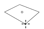
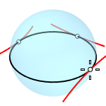
The ApplySphericalMapping command adds a texture mapping channel to an object and sets the mapping type to spherical.
Steps
- Select objects, and press Enter.
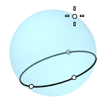
- Draw the mapping widget sphere.
- Enter a mapping channel number, or press Enter to accept the default value.
Command-line options
BoundingBox
Uses the object bounding box to determine the location and size of the mapping widget.
CPlane
Uses Construction plane coordinates for the bounding box.
World
Uses World coordinates for the bounding box.
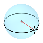
Radius
Creates a sphere by picking the center point and a radius point.
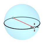
2Point
Creates a sphere from two opposite points on the base circle.
3Point
Creates a sphere from three points on the base circle.
Tangent
Creates a sphere with the base circle tangent to one, two or three curves.
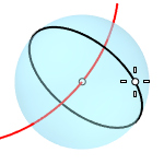
AroundCurve
Creates a sphere from its center point on a curve, and a point on the base circle perpendicular to the curve.
4Point
Creates a sphere from three points on a section circle and a point on the sphere.
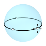
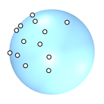
FitPoints
Creates a sphere by fitting to selected point objects, curve and surface control points, and mesh vertices.
| Toolbar | Menu |
|---|---|
|
|
|
The ApplySurfaceMapping command adds a texture mapping channel to an object and sets the mapping type to surface.
| Toolbar | Menu |
|---|---|
|
|
|
The ExtractUVMesh command creates separate mesh objects extracted from the flattened UV meshes of a model.
Input
Surface, Polysurface, Extrusion, Mesh, SubD.
Steps
- Select a supported object type.
- Specify a mapping channel.
- Draw a rectangle.
| Toolbar | Menu |
|---|---|
|
|
|
The MappingWidget command turns on the mapping widgets for the selected objects.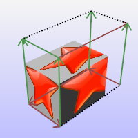
The box mapping widget:
- Shows graphically how the texture mapping is bound to an object using a primitive (box, cylinder, sphere, or plane).
- Can be dragged, moved, rotated, and scaled by normal Rhino commands.
- Can have its control points turned on to re-size it.
Command-line options
ShowOCSFrame
Displays the Object Coordinate System frame added to the object by the ApplyOcsMapping command.
This option is only visible when the selected object has an OCS frame.
| Toolbar | Menu |
|---|---|
|
|
|
The MappingWidgetOff command turns off the mapping widgets for selected objects.
Press to turn off all mapping widgets.
| Toolbar | Menu |
|---|---|
|
|
|
The MatchMapping command changes the texture mapping properties of a selected object to duplicate a specified object.
You can also use the Match Mapping button in Texture Mapping Properties.
| Toolbar | Menu |
|---|---|
|
|
|
The RemoveMappingChannel command removes the specified mapping channels from an object.
Steps
- Select objects.
- Type the mapping channel number.
| Toolbar | Menu |
|---|---|
|
|
|
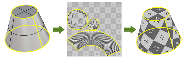
The Unwrap command prompts for selecting edges on the selected object as texture seams where the object's render mesh will be split in UV space.
Input
- Surface, Polysurface, Extrusion, Mesh, SubD
Steps
- Start the command.
- Select one or multiple objects, press .
Multiple selected objects will not overlap in UV space. - Select edges on the object.
Use the command-line options to help selecting edges. - Press when done.
Use the UVEditor command to edit the flatten render mesh in UV space to specify which portion of the material texture will display on the object.
Command-line options
Chain
Chain selects the seams.
PreviousSeamSelection
Reselects the previous set of seams.
Apply
Applies the seam selection.
Edit
Opens the UV Editor.
Cancel
Cancels the command.
MappingChannel
Selects a mapping channel number for the object.
UnweldedOnly (For mesh-only)
Makes only unwelded mesh edges selectable.
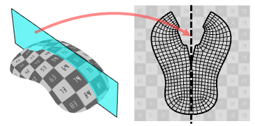
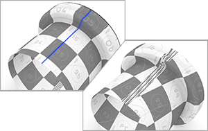
SymmetryTip
Defines the symmetrical plane on an object to unwrap the object symmetrically.
See the Rectangle command for sub-option descriptions.
UnweldSeams (Mesh-only)
Unwelds the mesh edges along the seams to avoid mapping distortion near the seams. The actual mesh geometry will be modified.
See Also
Materials and texture mapping in Rhino 6 for Windows
| Toolbar | Menu |
|---|---|
|
|
|
The UVEditor command edits meshes that affect the texture coordinates of the original object. The texture meshes can be joined and split, and their control points edited.
Steps
- Select objects.
- Draw a rectangular region on the world xy plane.
Command-line options
(Default)
Draws the rectangle using two opposite corners.
3Point
Draws the rectangle using two adjacent corner locations and a location on the opposite side.
EdgeMidpoint
Draws the rectangle from the midpoint of the first edge, an end of the edge, and a location on the opposite side.
Vertical
Draws the rectangle perpendicular to the construction plane.
Center
Draws the rectangle from the center point and a corner.
AroundCurve
Draws a rectangle perpendicular to a curve.
MappingChannel
The channel number of the texture mapping which will be edited.
FitLargeUVs
When the UV mesh is larger than the UV space rectangle, fits it into the rectangle, or leaves the UV mesh as it is (No).
-
The packed surface mapping texture coordinates are projected onto the world xy plane, and the texture assigned to the object is drawn in the same region.
-
The texture coordinates are represented as a collection of texture meshes.
-
When the texture meshes are edited, the texture changes on the object.
-
If an interior surface seam is selected in the polysurface prior to unwrapping, that seam will separate in the resulting flattened mapping meshes.
-
While the editor is open, control points for the mapping mesh objects can be turned on, and modeling commands such as Scale1D, SetPt, and CageEdit can be used to adjust the mapping mesh.

-
Meshes without UV coordinates (e.g., imported from STL files) do not have UV meshes to edit. You will need to unwrap the mesh, or apply a texture mapping to the mesh, before using the UVEditor command.
Texture transparency
Sets the transparency of the texture in the viewport for visibility.
Highlight selected
Highlights the surface mesh when the projected mesh is selected.
Show wireframe
Shows the mesh wireframe on the object even when in a viewport display mode that does not support displaying mesh wires.
Texture
Use material
Displays the texture associated with the diffuse channel of the material assigned to the object being unwrapped.
Use texture
Displays a specified texture from the Textures panel.
See also
Render
Render the objects using the current renderer.
Materials and texture mapping in Rhino 6 for Windows
About.com: Surfacing 101 - Texture Mapping
|
Toolbar |
Menu |
|---|---|
|
|
|
The ExtractCustomMappingObject command extracts the custom mapping source, a mesh or a surface, embedded in the selected object.