The Weld command removes creases from a mesh by merging coincident mesh vertices.
原來的網格頂點內含的貼圖座標、法線向量資訊會被平均/重建/破壞。
網格頂點熔接後由一個以上的網格面共用,頂點的法線為相鄰的網格面的法線的平均值。
指令行選項
角度公差
如果同一個網格的不同邊緣有頂點重疊在一起,而且網格邊緣兩側的網格面法線之間的角度小於角度公差設定值,重疊的頂點會以單一頂點取代。不同網格組合而成的多重網格在熔接頂點以後會變成單一網格。
改變角度公差時公差範圍內將被熔接的邊緣會以醒目提示。
The WeldEdge command removes creases from a mesh by merging coincident mesh vertices along selected edges.
指令行選項
復原
取消已選取的邊緣。
The WeldVertices command removes creases from a mesh by merging all selected mesh vertices.
The WeldVertices command lets you select mesh vertices to weld, rather than the entire mesh. It does not, however, give you a tolerance angle between faces to weld, like the Weld command does. You can window select by turning mesh points on and selecting the points prior to the command or you can run the command and then select multiple individual points.
網格頂點
頂點是網格面邊緣的匯集點,網格頂點包含 X、Y、Z 座標,也可能包含法線向量、色彩值及貼圖座標。
是否熔接網格頂點會影響彩現、網格上的貼圖對應及匯出給快速成型機的檔案。
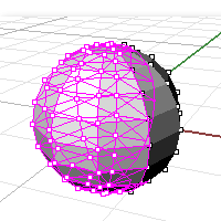
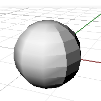
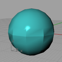
在框架模式下,這兩個網格物件看起來沒有什麼不同。
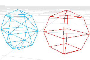
在彩現模式下,紅色的網格看起來比較平滑,而藍色的網格有明顯網格邊緣。
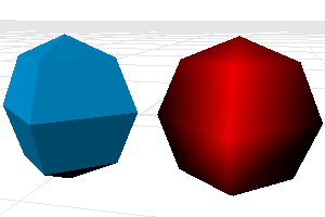
因為紅色網格上的頂點都熔接在一起,所以看起來比較平滑。藍色網格的頂點只是重疊在一起,並未熔接,所以每一個網格面的邊緣都清晰可見。
如果您想要讓藍色的網格看起來與紅色的網格一樣平滑。
您必需先決定網格的熔接角度公差,如果銳邊兩側的網格面之間的角度小於設定的角度公差,網格熔接後,原本在彩現模式下看到的網格邊緣會消失。
貼圖如何包覆在物件上是由貼圖座標所控制,貼圖座標會將貼圖的 2D 座標對應至網格頂點,然後依據頂點的數值將貼圖影像插入在相鄰的頂點之間。
點陣圖的左下角為原點,右下角的座標為 (1,0),左上角的座標為 (0,1),右上角的座標不 (1,1),貼圖座標的數值永遠都在這些數值以內。
每一個頂點只能含有一組貼圖座標,重疊的幾個頂點含有的幾組貼圖座標在熔接後只有一組貼圖座標會被留下來。
當一個網格的貼圖座標遺失後,您無法從該網格復原遺失的貼圖座標。
To remove welding (and to also lose the texture mapping coordinates), use the UnWeld or the UnWeldEdge command.
某些快速成型機只能讀取完全封閉 (水密) 的 STL 網格檔案。
You might want to use the Join command, then Weld (angle=180), then UnifyMeshNormals to turn a group of meshes into a single watertight mesh object, and use SelNakedMeshEdgePt to find the open (naked) edges. Following this procedure will ensure that the meshes really do fit together before exporting them for use in an expensive STL job.
See: Stereolithography (.stl) Import/Export.
The Unweld command adds creases to a smooth mesh by creating coincident vertices.
指令行選項
ModifyNormals=Yes/No
If Yes, the vertex normals on each side of the edge take the same value as the face to which they belong, giving the mesh a hard edge look.
If No, each of the vertex normals on either side of the edge is assigned the same value as the original normal that the pair is replacing, keeping a smooth look.
The UnweldEdge command adds creases to a smooth mesh by creating coincident vertices along selected edges.
指令行選項
ModifyNormals=Yes/No
If Yes, the vertex normals on each side of the edge take the same value as the face to which they belong, giving the mesh a hard edge look.
If No, each of the vertex normals on either side of the edge is assigned the same value as the original normal that the pair is replacing, keeping a smooth look.
網格是由兩個清單定義:
| ● | 一個是頂點的清單,內含頂點的屬性 (位置、法線、貼圖座標、頂點色)。 |
| ● | 另一個是面的清單,用來描述頂點如何連接形成面。 |
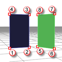
Quadrangular mesh
以下是描述圖中兩個獨立的四角網格面的兩個清單。
頂點清單
頂點清單對頂點的描述如下:
附註:這個例子已將貼圖座標與頂點色排除在外。
頂點 1 : 位置, 法線
頂點 2 : 位置, 法線
頂點 3 : 位置, 法線
頂點 4 : 位置, 法線
頂點 5 : 位置, 法線
頂點 6 : 位置, 法線
頂點 7 : 位置, 法線
頂點 8 : 位置, 法線
面的定義
面的清單對面的描述如下:
面 1 : 頂點 1, 頂點 2, 頂點 3, 頂點 4
面 2 : 頂點 5, 頂點 6, 頂點 7, 頂點 8
三角網格面的例子 (一)
以下是描述圖中兩個獨立的三角網格面的兩個清單。
頂點 1 : 位置, 法線
頂點 2 : 位置, 法線
頂點 3 : 位置, 法線
頂點 4 : 位置, 法線
頂點 5 : 位置, 法線
頂點 6 : 位置, 法線
面 1 : 頂點 1, 頂點 2, 頂點 3
面 2 : 頂點 4, 頂點 5, 頂點 6
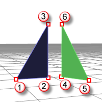
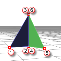
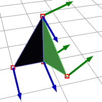
三角網格面的例子 (二)
以下是描述圖中兩個邊緣靠在一起的三角網格面的兩個清單。
頂點 1 : 位置, 法線
頂點 2 : 位置, 法線
頂點 3 : 位置, 法線
頂點 4 : 位置, 法線
頂點 5 : 位置, 法線
頂點 6 : 位置, 法線
面 1 : 頂點 1, 頂點 2, 頂點 3
面 2 : 頂點 4, 頂點 5, 頂點 6
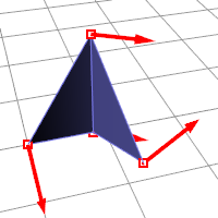
這個例子中的頂點 2 與 4 在同一個位置,頂點 3 與 6 也在同一個位置。
這兩個面有一個共同的邊緣,但是頂點 2、3、4、6 都有自己的屬性,所以這些頂點都有獨立的法線方向。
組合的網格
When you Join a mesh, the vertices and faces are in no way merged; the lists are simply appended. The face normals retain their direction.
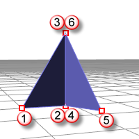
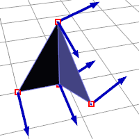
熔接的網格
When you Weld a mesh and the angle between the faces is below the threshold the common edge will be welded.
相同位置的頂點會被一個新的頂點與新的屬性取代:
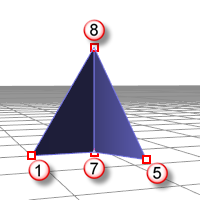
頂點 1 : 位置, 法線
頂點 5 : 位置, 法線
頂點 7 : 位置, 法線
頂點 8 : 位置, 法線
面 1 : 頂點 1, 頂點 7, 頂點 8
面 2 : 頂點 7, 頂點 5, 頂點 8
New normal attributes for vertices 7 and 8 are averaged based on the normals of the faces they are part of, so there is no way to get the previous (pre-weld) normals back.
摘要
請參考

