ToNURBS
| Toolbar | Menu |
|---|---|
|
|
|
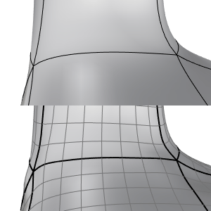
The ToNURBS command converts mesh objects and SubD objects/edges to NURBS surfaces or curves. It can also convert simple objects to NURBS for programs that only read NURBS. For example, Extrusion object is one of the simple object types. It is defined only by a profile curve and a length.
- The ToNURBS command replaces the ConvertExtrusion and MeshToNURB commands.
To create NURBS surfaces
- Select a mesh or SubD object.
To create NURBS curves
-
Hold down Shift+Ctrl and click mesh or SubD edges. Double-click to select an edge loop.
Command-line options
DeleteInputObjects
Yes
The NURBS object will replace the non-NURBS object.
No
The NURBS object will simply be added on the current layer. Both the old and new objects will be in the same location.
OutputLayer
CurrentLayer
Creates the NURBS object on the current layer.
InputLayer
Creates the NURBS object on the same layer as the input object.
MeshOptions (Mesh input only)
Click to set the options only used for mesh to NURBS conversion.
TrimTriangularFaces
Yes
Mesh triangles will be replaced by trimmed NURBS surfaces.
No
Mesh triangles will be replaced by untrimmed NURBS surfaces.
SubDOptions (SubD input only)
Click to set the options only used for SubD to NURBS conversion.
Faces
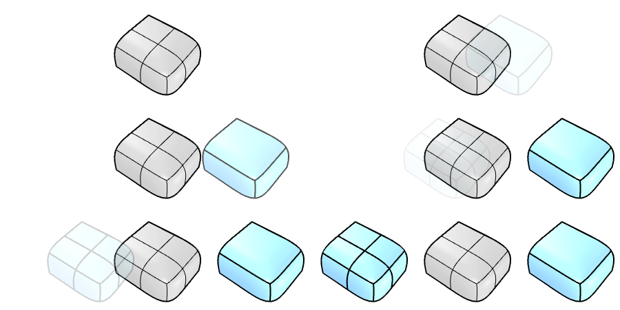
Specifies if quad face grids will be merged when converting a SubD into a polysurface.
Packed
Merges a quad face grid into a larger NURBS surface.
ShowFacePacks
Shows different colors on SubD faces based on the divisions of rectangular quad grids.
ForceUpdateFacePacks
Resets the rectangular quad grids after creases are added or faces are deleted on the SubD. It is equivalent to the PackSubDFaces command.
Unpacked
Creates a NURBS surface from each quad SubD face.
|
|
||
|
Unpacked
|
SubD
|
Packed
|
ExtraordinaryVertex
Continuity on a SubD at extraordinary vertices is G2. When converting a SubD to a polysurface, extraordinary vertices can only be approximated. This option controls the continuity of the polysurface at extraordinary vertices. Away from extraordinary vertices, the polysurface is always G2 in smooth SubD regions.
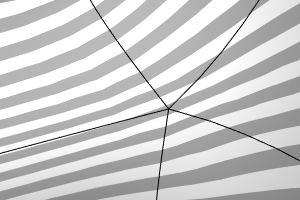
G0
Makes the polysurface G0 at the extraordinary vertices. The shape of the polysurface will be as close as possible to the SubD.
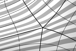
G1
Makes the polysurface G1 at the extraordinary vertices. The polysurface deviates from the SubD a little bit more than G0.
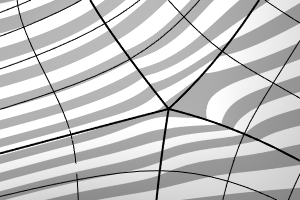
G1x
Similar to the G1 option, but tries to make the edge normal deviation around extraordinary vertices 1 degree or less.
G1xx
Makes the polysurface G1 at the extraordinary vertices and uses double knots on the isocurves near the edges. More control points will be added to improve the smoothness of Zebra stripes.
G2
Makes the polysurface G2 at the extraordinary vertices.
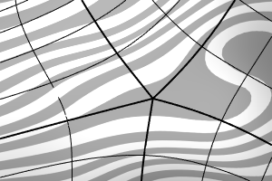
Forcing G2 adds bulges or dents around extraordinary vertices.
