Zebra
| Toolbar | Menu |
|---|---|
|
|
Analyze Surface > Zebra |
The Zebra command visually evaluates surface smoothness and continuity using a stripe map.
The Zebra command is one of a series of visual surface analysis commands. These commands use NURBS surface evaluation and rendering techniques to help you visually analyze surface smoothness, curvature, and other important properties.
Steps
- Set the stripe direction, size, and color.
- Set the stripe color to contrast with the base color of the object to see the zebra stripes.
The first stage is to set the detail level for the analysis mesh. You can increase the density of the mesh if the level of detail is not fine enough.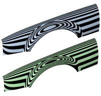

 Add Objects
Select more objects to analyze.
 Remove Objects
Remove selected objects from the analysis.
 Remove All Objects
Remove all objects from the analysis.
 Adjust Mesh
Open Analysis Mesh Options to change analysis mesh density. Increasing mesh density improves the analyzing accuracy.
 Restore Defaults
Reset the settings to the defaults.
 Help
Help
Open the help topic.
 Toggle Zebra Analysis Display
Show or hide zebra analysis display on evaluated objects.
Mode
The pattern style used for surface evaluation.
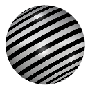
Stripes
Alternating stripes of two colors.
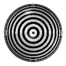
Radial
Thin stripes converging toward a central point.
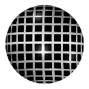
Grid
A pattern of rectangular cells.
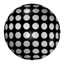
Dots
A pattern of rounded dots.
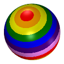
Rainbow
Stripes of rainbow colors.
 Static
Lock the pattern in place to prevent movement with view orientation.
Pick two points to define the static direction.
Set the World X, Y, or Z as the static direction.
Frequency
Control the density of the pattern.
Rotation
Adjust the pattern orientation by ±90 degrees.
Size
Adjust the scale or width of the pattern.
A value of 100% covers the background color as much as possible.
Blur
Control the softness of transitions between the background and foreground colors.
Background
The color behind the pattern.
Foreground
The color of the pattern.
Transparent background
Masks the underlying object portions beneath the background color.
Show wires
Display edges, isocurves, or wires of the object.
Interpreting the stripes
Position Only (G0)
If the stripes have kinks or jump sideways as they cross the connection from one surface to the next, the surfaces touch, but have a kink or crease at the point where the zebra stripes jag. This indicates G0 (position only) continuity between the surfaces.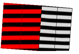
Tangent matches; curvature does not match (G1)
If the stripes line up as they cross the connection but turn sharply at the connection, the position and tangency between the surfaces match. This indicates G1 (position + tangency) continuity between the surfaces. Surfaces that are connected with the FilletSrf command display this behavior.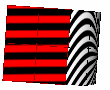
Position, curvature, and tangency match (G2)
If the stripes match and continue smoothly over the connection, this means that the position, tangency, and curvature between the surfaces match. This matching indicates G2 (position + tangency + curvature) continuity between the surfaces. Surfaces connected with the BlendSrf, MatchSrf, or NetworkSrf commands display this behavior. When you use surface edges as part of the curve network, the NetworkSrf options allow any of these connections.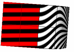
If, when you use the Zebra command, the selected objects do not already have a surface analysis mesh, an invisible mesh will be created based on the settings in the Polygon Mesh Options dialog box.
The surface analysis meshes save in the Rhino files. These meshes can be large. The RefreshShade command and the Save geometry only option of the Save and SaveAs commands remove any existing surface analysis meshes.
To properly analyze a free-form NURBS surface, the analysis commands generally require a detailed mesh.
| Toolbar | Menu |
|---|---|
|
|
|

The ZebraOff command turns off zebra analysis and closes the Zebra dialog box.
Steps
- Close the Zebra Options dialog box.