Patch
| Toolbar | Menu |
|---|---|
|
|
Surface Patch |
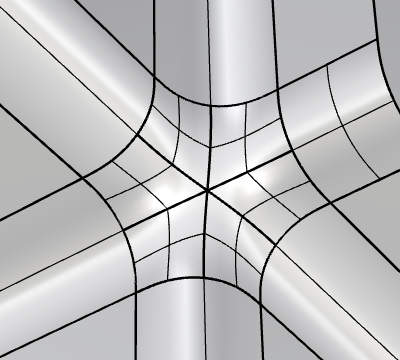
The Patch command uses surface edges, curves and points as input constraints to create a surface with positional (G0), tangential (G1) or curvature (G2) continuity to the input geometry.
Steps
-
Select curves, surface edges, or point objects, press Enter when done.
The input objects are labeled with I, G0, G1, or G2 that indicate the constraint levels.
-
Click the left or right mouse button on a label to cycle the constraint level forward or backward.
-
Set options.
Patch Options
 Show deviations
Uses Global Edge Continuity analysis to evaluate continuity between the patch surface and the input surfaces.
 Restore Defaults
Resets the settings to the defaults.
Click this button to select curves, edges, or points that define the boundary and interior shapes of the surface.
 Remove constraints
Removes all selected constraints.
-
Hover over the green check-mark to reveal a red cross that will clear all constraints.
Set all constraints (G0/G1/G2)
Applies the same constraint level to all boundary edges of the patch surface.
Alternatively, you can hold Shift and left- or right-click a boundary label to do the same.
Constraint level for curves and points
-
Internal curves can be set to either G0 or I (Int).
In order to trim the patch surface with the boundary, I (Int) must be set for internal curves.
-
Points can only be set to I (Int).
Stiffness
Controls the roundness and flatness of the surface shape. Higher values produce flatter shapes.
-
Double-click the slider to enter a specific number.
Degree
Sets the UV degrees of the surface from 3 to 5.
Domain
The domain option is used to create a trim domain on the surface that outlines the patch.
Untrimmed
Creates an untrimmed surface. This option is only available when the input segments on the boundary can be merged into four smooth segments.
Projected
Suitable for input objects that are more or less planar; this option is selected automatically if that is the case.
Molded
Default for all other cases. This option creates the best trimming domain for curves that are less planar.
MultiBlend
Uses multiple untrimmed surfaces, rather than a single trimmed surface, to fill the boundary.
-
You can use a point object as an internal constraint to change the center position of the patch surfaces,
or a line to change the center position and its normal direction.
-
Some options are disabled or have no effect in MultiBlend mode.
Refine
Uses more UV spans to better fit the surface to the input edges or curves.
Preview
Displays an interactive preview of the surface before it is created. Turn it off to avoid triggering a re-calculation when options are changed.
UV Control
UV Rotation
Rotates the UV directions of the surface up to 90 degrees.
-
Double-click the slider to enter a specific number.
U Spans / V Spans
Sets the initial number of isocurves along the U or V direction.
-
Turning on the Refine setting adjusts the isocurve density to meet the specified tolerances.
Input surface
Pick an existing surface that will be pulled to fill the boundary.
Click the ![]() button to remove the selected surface.
button to remove the selected surface.
-
The output surface will have an identical parameter structure to the starting surface.
-
Using a starting surface allows you to create a surface with a degree higher than 5.
Delete input
Deletes the selected starting surface after the patch is created.
Preserve edges
Keeps the starting surface’s boundary edges unchanged.
Tolerances
Distance
Controls position matching accuracy.
Angle
Controls tangency matching accuracy.
Internal
Controls the matching accuracy to internal curves or points.
Constraints test results
These labels use green check marks and red cross marks to indicate whether the resulting surface meets the requested tolerances of Int (internal), G0 (Position), G1 (Tangency), and G2 (Curvature). No mark means the test was not run.
To edit the output surface
-
Double-click the output surface.
-
Add or remove curves or edges, press Enter.
-
Adjust the options.