FlowAlongSrf
| Toolbar | Menu |
|---|---|
|
|
Transform Flow along Surface |
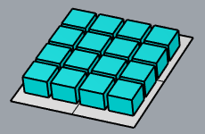
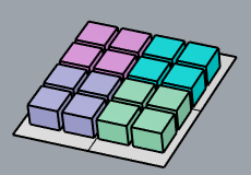
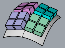
The FlowAlongSrf command morphs objects from a source surface to a target surface.
Steps
- Select objects.
- Select the edge of the base surface near a corner.
- Select the edge of the target surface near a matching corner.
-
When object grips are flowed to a surface with History recorded, History will not update the child object when the grips are off on the parent object.
-
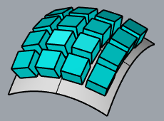
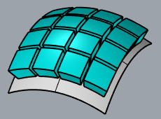
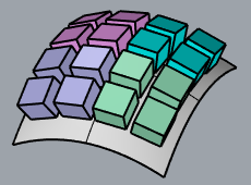
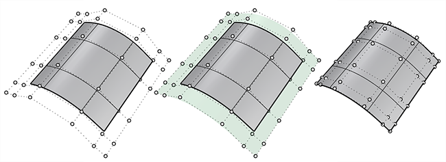
The base and target surfaces need to have even parameterization to avoid stretching the objects.
 In this example, parameterization of the target surface (1) is not even. That causes the objects to stretch.The target surface (2) is rebuilt with dense isocurves. Even parameterization avoids obvious stretching to the objects.
Command-line options
Copy
Specifies whether or not the objects are copied. A plus sign ![]() appears at the cursor when copy mode is on. The RememberCopyOptions command determines whether the selected option is used as the default.
appears at the cursor when copy mode is on. The RememberCopyOptions command determines whether the selected option is used as the default.
Rigid
Decides if objects are only relocated, but not deformed, along the target surface.
Yes
No
RigidGroups
Decides using groups or individual objects to rigid. Only available when Rigid=Yes.
Yes
No
Plane
Draw a plane instead of using an existing surface as the base objects.
See the Rectangle command for detailed option descriptions.
ConstrainNormal
Specifies how the normal direction of the base surface is mapped onto the target surface.
Yes
Pick two points to define the constraint direction.
Press Enter to use the CPlane-Z of the viewport where the target surface is picked.
No
Use the target surface normal.

AutoAdjust
Yes
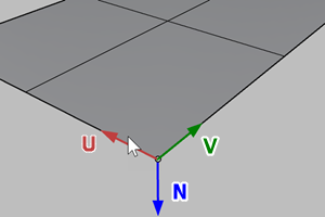
- Ignores the UV directions of the base and target surfaces. The corner and edge near the picking location define the origin and U direction. The other direction will be the V direction. The N direction is defined from UV directions by the Right-hand rule.

The object may be mapped onto the opposite side of the target surface if the picking locations on the base and target surfaces don't match.
- If the base or target surface is trimmed, the shrunk version of the surface is used for mapping the object.
No
- Uses the UV directions of the base and target surfaces to map the object onto the target surface. The picking locations on the base and target surfaces are not critical. The N direction is defined from UV directions by the Right-hand rule.
- If the base or target surface is trimmed, the underlying surface is used for mapping the object.
PreserveStructure
Specifies whether the control-point structure of a curve or surface will be maintained after the deformation.
The PreserveStructure option does not apply to polysurfaces, and will not be displayed if polysurfaces are selected for editing.
Yes
The control point structure of the surface is maintained. Deformation may be less accurate if there are too few control points in on the object.
No
The objects are refit as needed with more control points to allow accurate deformation.
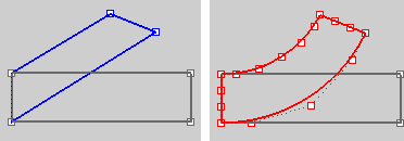
PreserveStructure=Yes (left); PreserveStructure=No (right).