Mesh
| Toolbar | Menu |
|---|---|
|
|
Mesh From NURBS Object |
The Mesh command creates a polygon mesh from a NURBS surface, polysurface, or SubD.
A mesh is a collection of vertices and polygons that define the shape of an polyhedral object. Meshes in Rhino consist of triangles and quadrilaterals.
Rhino creates triangles and quadrilaterals meshes for exporting to various file formats. If a mesh is generated from a solid, the mesh will be seamless/watertight.
Note
- The meshes created by the Mesh command are editable, and separate from the objects they were created from.
- The meshes created by shaded viewport display modes are not editable. They can be extracted with the ExtractRenderMesh command.
Seamless (watertight or closed) mesh
Rhino creates triangles and quadrilaterals meshes for export into various file formats. When surfaces are joined together in Rhino, the meshes along the joined edge have coincident vertices. If a mesh is generated from a solid, there will be no holes in the mesh. This is valuable for export to STL rapid prototyping files.
Steps
-
Select surfaces, polysurfaces, or SubD objects.
-
Preview the mesh and set mesh options.
Fewer polygons  More polygons
The slider controls the density of mesh faces created from NURBS surfaces, and the adaptive meshing levels of SubD objects.
Mesh wires are drawn in viewports for preview, and the dialog box stays on screen for more adjustments.
Switches the dialog box to the detailed meshing settings.
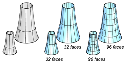
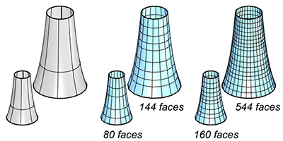
How NURBS surfaces are converted to meshes?
Meshing a surface or polysurface in Rhino happens in up to four steps:
-
The first step creates a regular rectangular grid of vertices on the surface. If the surface is trimmed, the shrunk copy of the surface is used for this step. The spacing of this grid can vary along each direction, and is estimated to roughly meet the meshing criteria set in NURBS meshing parameters.
-
The second step refines the grid by subdividing some quadrangles of the initial grid until each quadrangle meets the meshing criteria. This step does nothing if “Refine mesh” is false.
-
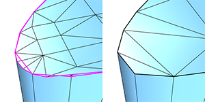
The third step trims the mesh along the trimmed surface edges. This step does nothing if the object being meshed is a single untrimmed surface.
-
The fourth step combines coincident vertices along the joined surface edges to fill the gaps. This step does nothing if “Jagged seams” is true or if the object being meshed is not a polysurface.
All vertices generated by the meshing process are exactly on the surface. Meshing error is typically measured as the distance between the mesh edges midpoints and the surface.
In the first step, all mesh faces are quadrangles. In all further steps, new triangular faces can be introduced in the mesh. Only the second step can introduce new mesh vertices in the interior of the meshed surface. Step three and four can introduce new mesh vertices on edges.
NURBS meshing parameters
Many of these parameters are shared between the first and second steps. All steps except the fourth are run independently for each face.
Density
Density is the parameter controlled by the slider in the simple mesh controls dialog. It uses a formula to control how close the polygon edges are to the original surface. The default value is 0.5, and acceptable values are between 0 and 1. Larger values result in a mesh with a higher polygon count.
The formula is based on the size of the surface being meshed, and is used to generate a per-surface value for the Maximum distance, edge to surface parameter. This value will be smaller as the Density setting gets closer to one, and for smaller surfaces. If there is also an explicit non-zero Maximum distance, edge to surface value set in the dialog, then the mesher will use the smallest number for each surface.

Maximum angle
In the initial grid step, this value controls the approximate maximum angle made by the surface normals at neighboring mesh vertices. Two vertices are neighbors if they are at the opposite ends of a single edge. In the mesh refinement step, quadrangles are subdivided until the angle between surface normals is smaller than this value.
This setting will influence the meshing of objects of the same shape in the same way regardless of the size of the objects. It will tend to make meshes denser in areas of high curvature and less dense in flatter areas. Setting this value to 0 disables the criterion. The default value is 0°, and the suggested range is from 5° to 90°.
This setting is scale independent.
Maximum aspect ratio
In the initial grid step, this value controls the approximate maximum aspect ratio of the quadrangles. In the mesh trimming step, this value controls when to subdivide quads that would otherwise become too skinny when trimmed.
Smaller values result in slower meshing and a higher polygon count with more equilateral and nicely shaped polygons. Setting this value to 0 disables the criterion. The default value for this option is 0 and the suggested range, when not 0, is from √2 to 100.
This setting is scale independent.
Application
When shading long, skinny objects, use 0 for this value. This allows infinite ratios. Control the smoothness of the mesh with other parameters.
Minimum edge length
In the initial grid step, this value controls the approximate minimum edge length of the quadrangles. In the refinement step, if any edge is shorter than this value, no further division of the mesh faces occurs.
The default value for this option is 0.0001 system units and the usable range depends on the size of the model. Bigger values result in faster meshing, less accurate meshes and a lower polygon count. Setting this value to 0 disables the criterion.
This setting is scale dependent.
Maximum edge length
In the initial grid step, this value controls the approximate maximum edge length of the quadrangles. In the refinement step, quadrangles are further divided until all edges are shorter than this value.
Smaller values result in slower meshing and a higher polygon count with more equally sized polygons. Setting this value to 0 disables the criterion. The default value is 0 and the usable range depends on the size of the model.
This setting is scale dependent.
Application
Use for making sure the polygons are approximately the same size.
Maximum distance, edge to surface
The distance is calculated from a mesh edge midpoint to the surface. In the initial grid step, the grid will approximately match this criterion. In the mesh refinement step, quadrangles are subdivided until the distance from a polygon edge midpoint to the surface is smaller than this value.
Smaller values result in slower meshing, more accurate meshes, and a higher polygon count. Setting this value to 0 disables the criterion. The default value is 0 and the usable range depends on the size of the model.
This setting is scale dependent.
Application
Use as a general polygon mesh tolerance setting.
Minimum initial grid quads
The minimum number of quadrangles per surface in the initial mesh grid. Note that value applies to the shrunk untrimmed surface, so trimmed surfaces can use fewer quadrangles than this value.
Bigger values result in slower meshing, more accurate meshes and a higher polygon count with more evenly distributed polygons. Setting this value to 0 disables the criterion. The default value is 0 and the suggested range is from 0 to 10000.
This option is scale independent.
Application
Use to make sure that surfaces with very subtle details are meshed with a high enough polygon count.
Refine mesh
If this option is true, in the mesh refinement step, Rhino uses a recursive process to refine the mesh by subdividing quadrangles until they meet the criteria defined by the Maximum angle, Minimum edge length, Maximum edge length, and Maximum distance, edge to surface options.
No refinement results in faster meshing, less accurate meshes, and lower polygon count. No refinement also means untrimmed individual surfaces and surface areas away from trim edges and joined edges are meshed with evenly sized quadrangles.
Refinement is disabled for extrusions and ruled surfaces.
Jagged seams
If this option is true, all surfaces are meshed independently and Rhino does not stitch the edges between joined surfaces.
Meshes for each surface in a polysurface do not necessarily meet to form a watertight mesh. This causes faster meshing, a lower polygon count and cracks between joined surfaces in the rendered image.
If this option is false, watertight meshes are created.
Application
The Rhino mesher does not support watertight meshes made only of quadrangles unless you are meshing a single untrimmed surface. In this case, clear Refine mesh and use Jagged seams to generate quadrangle meshes.
Simple planes
If this option is true, all planar surfaces are meshed by meshing the surface edges and then filling the area bounded by the edges with triangles. This causes a slower meshing and a minimum polygon count on planar surfaces, especially for complex trimmed surfaces.
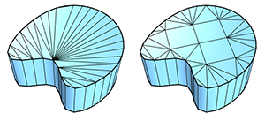
If this option is true, all other settings except for Jagged seams are ignored for planar surfaces, and the planar surface is meshed with as few polygons as possible.
Pack Textures
If this option is true, Rhino packs the mesh textures of the meshed polysurfaces.
SubD meshing parameters for raytracing
Level
This setting controls the adaptive or absolute subdivision level of the meshes converted from SubD objects. A smaller level results in faster meshing, less accurate meshes, and lower polygon count. The default value is 4 and the accepted range is 1 to 5.
Mesh wires are drawn in viewports for preview, and the dialog box stays on screen for more adjustments.
Switches the dialog box to the simple meshing settings.