The Layout command creates a print layout viewport.
A layout viewport represents the sheet of paper that will be sent to a printer or a file such as PDF. Layouts can include various views of the model and annotations like title blocks and notes.
Two types of viewports provide different functions: model viewports and layout viewports.
In model viewports, create your surface or solid model using the appropriate units and precision.
In layout viewports, place one or more details of your model and add information that annotates the printed sheet, such as manufacturing notes, bill of materials, general notes, title blocks, seals, and scale bars.
These viewports are accessible on the tabs at the bottom of the modeling area. The ViewportTabs command turns the tabs on and off.
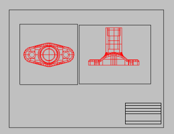
Detail viewports
Layout viewports contain detail viewports. Detail viewport contain a view of the model. Details have their own viewport properties and object properties. The color, width, and other properties of the detail viewport edge including the No Print property are object properties of the detail.
Name
The layout viewport name.
Select Printer
Printer
Select the target printer from the list of configured Windows printers.
Size
Select a supported paper size from the list.
Portrait/Landscape
Sets the orientation.
Width/Height
Sets the size of the paper as well as the width (x length) and height (y length) of the layout. If the paper size not support by the selected printer, the Printer setting will be disabled.
<inches>
Units for the paper size.
Initial Detail Count
The number of details to start with.
Steps
| 1. | In the New Layout dialog box, specify options. |
| 2. | Draw a border or insert a title block onto the layout. Add text that does not relate to the model such as the project name, sheet number, sheet content, and the like.
|
| 3. | Add annotation objects such as text and title blocks. |
| 4. | Create details and arrange them on the layout. |
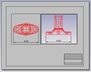
| 5. | In each detail set up view of the model, orientation, and scale.
|
| 6. | In the detail viewport, add text and dimensions that apply to the model geometry.
|
Note: To correctly reflect model geometry, add dimensions in the detail viewport. Text added here relates to and reflects the model rather than the layout. For example, if a beam is labeled as M8X6.5, it needs to be in the detail viewport.
| 7. | Set the visibility of the detail edge on the printed page. Use Properties to access the Print WidthNo Print property.
|
| 8. | Print. |
The ImportLayout command imports one or more layouts from a Rhino file into the current Rhino model.
This allows defining standard title block pages in a single file and importing those pages into other Rhino files.
The CopyLayout command copies the active layout to a new layout.
The LayoutProperties command opens the Modify Layout dialog box.
See also
Rhinoceros 5 © 2010-2015 Robert McNeel & Associates. 17-Sep-2015