![]()
![]()
Edit
Rebuild
| Toolbar | Menu |
|---|---|
|
|
Edit Rebuild |
The Rebuild command reconstructs selected curves or surfaces to a specified degree and control point number.
Rebuild options
Reports in parentheses the current number and sets the number of control points in the result.
Reports in parentheses the current number and sets the degree of the curve.
When drawing a high-degree curve, the output curve will not be the degree you request unless there is at least one more control point than the degree.
Deletes the original geometry.
Creates the new objects on the current layer. Clear this check box to place the new objects on the layer of the original curves.
Reports the maximum deviation from the original curve when Preview is clicked.
Displays a preview of the output.
If you change the settings, click the button again to refresh the display.
| Command-line options | |
|---|---|
|
SelectMasterCurve |
Select a curve to use as a template for setting the point count and degree. |
Rebuild Surface Options
Reports in parentheses the current number and sets the number of points in the u direction.
Reports in parentheses the current number and sets the number of points in the v direction.
Reports in parentheses the current number and sets the degree in the u direction.
Reports in parentheses the current number and sets the degree in the v direction.
Deletes the original geometry.
Creates the new surfaces on the current layer. Clear this checkbox to place the new surfaces on the layer of the original surfaces.
Trims the rebuilt surface with the original trimming curves.
Reports the maximum deviation from the original surface.
The calculation tests how far away the new surface is at knot line intersections and half-way between knot lines. Conducts tests at knot line intersections and halfway between knot lines.
The display color indicates how far away the new surface is from the original. Points are green if the surface is within absolute tolerance, yellow if it is between tolerance and 10 times tolerance, and red if it is farther away than that.
Displays a preview of the output.
If you change the settings, click the button again to refresh the display.
| Toolbar | Menu |
|---|---|
|
|
|
The RebuildUV command reconstructs selected surfaces to a specified control point number in either the u or v directions independently.
| Command-line options | |
|---|---|
|
Direction |
Specify the u, v, or both directions. |
|
PointCount |
Specifies the number of control points in the result. |
|
Type |
LooseThe surface control points are created at the same locations as the control points of the original. This is a good option if the control points will be edited later. NormalThe surface has an average amount of stretching between the curves. This is a good choice when the curves are proceeding in a relatively straight path or there is a lot of space between the curves. Straight sectionsCreates a ruled surface. The sections between the curves are straight. TightThe surface closely follows the original. This is a good choice when the input curves are going around a corner. UniformMakes the object knot vectors uniform. |
|
DeleteInput |
YesDeletes the original geometry. NoRetains the original geometry. |
|
CurrentLayer |
The output will be on the current layer. |
| Toolbar | Menu |
|---|---|
|
|
|
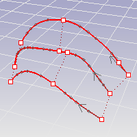
The RebuildCrvNonUniform command interactively modifies selected curves by non-uniformly re-spacing the control points.
| Command-line options | |
|---|---|
|
RequestedTolerance |
Specifies the maximum distance the rebuilt curves can deviate from the originals. If you do not provide enough control points, the rebuilt curves may deviate more than RequestedTolerance from the originals. The maximum deviation from the original curves is reported at the command line and marked with a point on the curve. |
|
MaxPointCount |
Specifies the maximum number of control points per curve used to rebuild. |
|
Quarters |
Displays two more controls along each curve to influence how the RebuildCrvNonUniform command distributes control points. The controls at the end of the curves can be used to shorten the resulting curves. |
|
DeleteInput |
YesDeletes the original geometry. NoRetains the original geometry. |
|
ResetPoints |
Resets the editing points to their original locations. |
Rhino for Mac © 2010-2017 Robert McNeel & Associates. 24-Oct-2017
