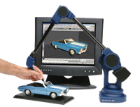
Use a digitizing arm
Digitizing arms are used to capture point data from a physical object in order to make a 3‑D virtual model of the object.
Before you start using a digitizing arm, you must initialize and calibrate the digitizer.
You can calibrate digitizers so that a coordinate system in the real world corresponds to a coordinate system in Rhino. The calibration can change in the middle of the digitizing process to allow digitizing of the underside of an object, or an object that is larger than the reach of the digitizer.
You can set the scale factor for digitized points. By default, one inch in the real world is one Rhino unit.
Digitizers use a foot pedal to pick points.
The DigClick command allows you to pick points from within Rhino. You can set up a function key (such as F12) so that when you press the function key, it is as if you pressed the foot pedal.
Commands for setting up a digitizing arm
DigBeep
Turn the digitizing arm sound on and off.
DigCalibrate
Validate digitizer measurements against a model.
DigCamera
Set the view based on the probe position and direction.
DigDisconnect
Disconnect the digitizing arm.
Digitize
Connect and initialize a digitizing arm.
DigScale
Set a scale factor for digitized points.
Commands for using a digitizing arm
DigClick
Pick a location with a digitizing arm.
DigLine
Draw a line normal to a surface with a digitizing arm.
DigPause
Suspend/pause input from the digitizing arm.
DigSection
Create planar cross sections with a digitizing arm.
DigSketch
Sketch a curve with a digitizing arm.
Use a custom tip with a MicroScribe
- In MicroScribe Utility Software (MUS), open the Configuration dialog.
- Select the Custom Tip tab.
- Select Use Custom Tip and add your custom tip.
- Close MUS.
- In Rhino, run the MicroScribeSelectTip command and select the custom tip.