GeometricTolerance
|
Toolbar |
Menu |
|---|---|
|
|
Drafting Other Annotations > Geometric Tolerance |
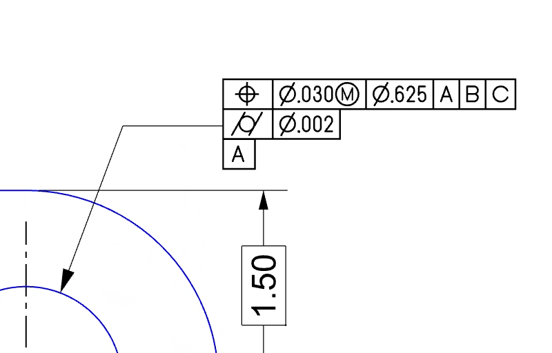
The GeometricTolerance command creates a geometric-tolerance feature control frame as an annotation text object in the model. It opens a dialog where you can define the GD&T parameters, including geometric symbols, tolerance values, material conditions, etc. Geometric tolerances are crucial for ensuring that parts are manufactured within acceptable limits and can be assembled correctly.
Steps
-
Run the GeometricTolerance command.
-
Fill out the fields in the editor as needed, then click OK.
-
Pick a location in the viewport to place the feature control frame.
-
A “Geometric Tolerance” annotation style is added to the model to control the appearance of feature control frames. The style uses a special GD&T font by Peter Kanold which can draw boxed characters, align those boxes, and construct the formatted strings required to display geometric tolerances correctly.
-
Double-clicking an existing feature control frame runs the GeometricToleranceEdit command to edit its contents. You can directly edit the content in its text object properties as well.
|
Toolbar |
Menu |
|---|---|
|
|

The GeometricToleranceEdit command modifies existing geometric-tolerance feature control frames.
-
Double-clicking an existing feature control frame runs this command.