Accurate modeling
Normally, dragging the mouse moves the cursor on the construction plane in the active viewport. Simply move the cursor to another viewport to change the construction plane.
You can also restrict the cursor movement in a number of ways, including:
- To a distance
- To an angle
- Vertical to the construction plane
- To a specified coordinate point
- To a coordinate point relative to the current location
- In a specified direction based on the cursor location
- To the x, y, or z coordinate of specified location
Distance constraint
Locks the next point at a specified distance from the last point.
To constrain to a single distance
Use distance constraint to draw a line
Angle constraint
Locks the next point will be placed at a specified angle relative to the last point.
Constrain to an angle
- Type an angle at the command prompt in the format <angle and press Enter.
The cursor moves along a line at the specified angle.
The angle constraint can also be used for finalizing the pick in elevator mode.
Use angle constraint to draw a line
Distance and angle constraint used together
The distance and angle constraints can be combined.
To use both distance and angle
- At a prompt type the @ symbol, or type r to set the distance relative to the last point.
Use distance and angle to draw a line
- Start the Line command, and place the first line point.
- At the End of line… prompt, type @5<45 or r5<45.
The line is drawn 5 units from the last point at the angle 45 degrees from the first point.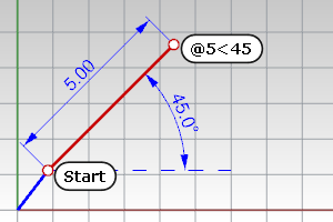
Direction lock (Tab key)
The Tab key locks the cursor's direction of travel.
To use direction lock
- When drawing, after placing the first point, drag the mouse to a new location and tap the Tab key to lock the direction.
Draw a line using direction lock
- Start the Line command, and place the first line point.
Use an object snap to locate a specific location on another object. - Tap the Tab key.
The marker is now constrained along the line between the first point and the point where the marker, was when you tapped the Tab key.
If grid snap is on and ortho is activated, the direction lock snaps to grid lines.
Tips
- Use the direction lock constraint when you want the line to pass through the end of a curve and then go beyond it. Turn on end object snap. When you move the cursor close to the end of the curve, the marker snaps to the curve end. Tap the Tab key and then move the mouse beyond the curve end and pick. The line will pass through the end of the curve.
- Use direction lock constraint combined with the distance constraint to draw a curve of a specified length and then constrain the angle with the Tab key.
Circle lock (Tab key)
A second tap of the Tab key will set Rhino into a tracking mode on a circle where, instead of locking to a line defined by the last pick point and the 3‑D mouse location when the Tab key is tapped, Rhino tracks to a circle with the center at the last pick point and the radius defined by the Tab tap location.
To use circle lock
- When drawing, after placing the first point, drag the mouse to a new location and tap the Tab key twice to lock the circle radius.
Toggle SubD display (Tab key)
When no command is asking for picking a direction, pressing the Tab key toggles all SubD objects in the model between the box (flat) and smooth modes.
SubDDisplayToggle
Switches the appearance of all SubD objects between box (flat) and smooth modes.
Elevator mode
Specify a point that is a given distance above or below a point on the construction plane.
Ctrl + left mouse click.
Draw a curve using elevator mode
- Start the Curve command and place the first point.
- At the Next point of curve... prompt, pick another location in the perspective viewport.
- At the Next point... prompt, hold Ctrl and pick a point in the perspective viewport.
- Drag the mouse in the perspective viewport.
A tracking line displays, indicating that the marker is constrained to move perpendicular to the construction plane. Click to select the point. Notice the location of the marker in the other views.
Drag objects perpendicular to the construction plane using elevator mode
Turn off elevator mode if you have started elevator mode in error
- After starting elevator mode, hold Ctrl and click the left mouse button again.
- Continue with picking locations.
You can start elevator mode in another location.
Example with angle and elevator mode
- Start the Line command and place the first line point.
- At the End of line… prompt, move the mouse to the location where the line should end.
- Hold down Ctrl and click to activate the Elevator mode.
- Release Ctrl, type <30 and press Enter.
A line is drawn at 30 degree angle to the construction plane, ending on the elevator line.
Other ways to use elevator mode
Multiple elevator
Canceling elevator
Elevator from direction lock
Elevator mode can also be activated from direction lock, but only if the command allows 3‑D points.
Note
- Type a number at the command prompt to specify the elevation of the point. Positive numbers are above the construction plane, negative numbers are below.
- Specifying 3-D points using 2-D input devices (the mouse and monitor) is aided with construction planes. Anything drawn in Rhino by simply picking points is always drawn on the construction plane of the current viewport.
Point filters
Point filters extract individual x, y, and z coordinate values from different points to create a new, composite point.
You can use point filters to pick one coordinate value at a time while temporarily ignoring other coordinate values. If you use point filters with object snaps, they extract coordinate values from an existing object so you can locate another point.
After you specify the first value, you are prompted for the remaining values.
Point filters only work when 3-D input is allowed, and you cannot start with one point filter and then apply another one.
The following filters are possible:
.x
.y
.z
.xy (.yx)
.xz (.zx)
.yz (.zy)
.wx
.wy
.wz
.wxy (.wyx)
.wxz (.wzx)
.wyz (.wzy)
Draw a point using filters
To place a point at the x coordinate of the right end of a line and the y coordinate of the left end of a line.
- Start the Point command.
- At the Location of point object prompt, type .x.
- At the X coordinate of prompt, with the End object snap activated, pick the right end point of the line.
- This sets the x coordinate of the point to the right end of the curve.
- At the next Location of point object prompt, type .y.
- At the Y coordinate of prompt with the End object snap activated, pick the left endpoint of the line.
This sets the y coordinate of the point to the left end of the curve. - At the Location of point object prompt, pick to place the point.
If you specified an x value, the coordinate of the new point matches the x value of the first point and the y, z value of the second point.
Entering numbers
Use numbers for entering distances, angles, and point coordinates.
No spaces are permitted in a number, angle, or x, y, z coordinate points.
Basic numbers
Whole numbers
123
Decimal numbers
123.456
0.456
.456
Scientific notation
-1.23456e10
1.23456E10
Fractions
5/16
1-3/4 (1.75)
Units
You can specify units when typing lengths and point coordinates. The numbers will automatically convert to the model's units. For example, if your model units are meters, and you type 27cm, Rhino automatically converts your number to 0.27. This also works for converting feet and inches or any other unit system.
Unit examples
1.235millimeters
-1.234cm
+16'5" (16 feet 5 inches)
1'2-3/4" (1 foot 2.75 inches)
Cartesian coordinates
When prompted for a point, you can click the mouse in a viewport to define the point coordinates or you can or type the coordinates in several ways:
You can type x and y coordinates or x, y and z coordinates to place points. With the w prefix you can type world coordinates, with r prefix relative coordinates, and with wr prefix world relative coordinates.
Construction plane coordinates
When Rhino prompts you for a point, if you type x and y Cartesian coordinates, the point will lie on the construction plane of the current viewport.
Use 2-D construction plane coordinates
- At a prompt, type the coordinate in the format x,y where x is the x coordinate and y is the y coordinate of the point.
Use 3-D construction plane coordinates
- At a prompt, type the coordinate in the format x,y,z where x is the x coordinate, y is the y coordinate, and z is the z coordinate of the point.
There are no spaces between the coordinate values. - To place a point 3 units in the x direction, four units in the y direction, and 10 units in the z direction from the construction plane origin, type 3,4,10 at the prompt.
If you enter only x and y coordinates, the point will lie on the construction plane.
Examples
x,y,z
3,4,5
2,-11 (2,-11,0) When you omit the z coordinate, it is automatically set to 0.
If you type only x and y coordinates, the point will lie on the construction plane of the active view.
Use construction plane coordinates
- At a prompt for a point, type coordinates in the format x,y,z and press Enter.
Note
- 0 (zero) is a shortcut for 0,0.
- There are no spaces between the coordinate values.
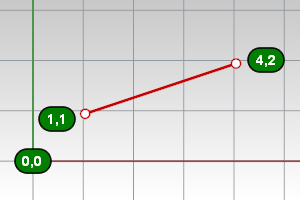
Use construction plane coordinates to draw a line
- Start the Line command and place the first line point at 0,0.
This starts the line at the construction plane origin. - At the End of line... prompt, type 12,6,10 and press Enter.
The line is drawn from the construction plane origin to a point 12 units along the x-axis, 6 units along the y-axis, and 10 units along the z-axis of the current construction plane.
World coordinates
Rhino contains one world coordinate system. The world coordinate system cannot be changed. When Rhino prompts you for a point, you can type coordinates in the world coordinate system.
The arrow icon in the lower left corner of each viewport displays the direction of the world x, y, and z axes. The arrows move to show the orientation of the world axes when you rotate a view.

Use 2-D world coordinates
- At a prompt, type the coordinate in the format wx,y, and press Enter.
Use 3-D world coordinates
- At a prompt, type the coordinate in the format wx,y,z, and press Enter.
- To place a point 3 units in the world x direction, 4 units in the world y direction, and 10 units in the world z direction from the world origin, type w3,4,10 at the prompt.
Note
- w0 is a shortcut for w0,0,0.
- There are no spaces between the coordinate values.
Examples
Type w in front of the coordinates, to use the world coordinate system; otherwise the construction plane coordinates of the active view are used.
World x,y,x
w9,3,4
Use world coordinates to draw a line
Relative coordinates
Rhino remembers the last point used, so you can enter the next point relative to it. Relative coordinates are useful for entering a list of points where the relative locations instead of absolute locations of the points are known. Use relative coordinates to locate points according to their relationship to the previous active point.
Use relative coordinates
- At a prompt, type the coordinates in the format rx,y where r signifies that the coordinate is relative to the previous point.
Use relative coordinates to draw a line
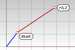
Example
In commands like Line and Polyline, you can specify relative points.
Relative construction plane
@3,4 (Move 3 units in the x direction and 4 units in the y direction from the previous point.)
r3,4
Relative world
w3,4
Polar coordinates
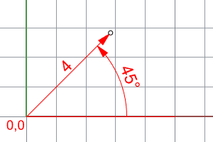
Polar coordinates specify a point that is a distance and direction away from 0,0 in the current construction plane. Vector directions in Rhino start with zero degrees at 3 o'clock on a standard clock. They change in an anti (counter)-clockwise direction as illustrated below.
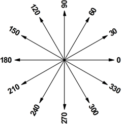
If you want a point four units away from the construction plane origin (0,0), at a 45° angle counterclockwise from the x-axis, type 4<45, and press Enter.
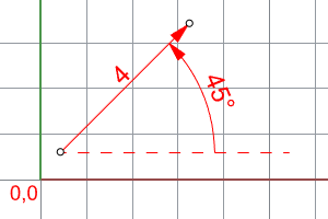
Relative polar coordinates are preceded by R or @. To place a point at four units away from the previous point at a 45° angle counterclockwise from the x-axis, type @4<45, and press Enter.
Example
Polar (distance<rotation angle)
17<45
@17<45, or r17<45
w17<45
rw17<45
Polar and elevation (distance<rotation angle,z)
17<45,8
@17<45,8, or r17<45,8
w17<45,8
rw17<45,8
Other coordinates
Spherical (distance<rotation angle<z elevation angle)
5<30<45
Spherical (x,y<elevation angle)
5,6<15
Surveyor (distance<N/Sangle E/W)
11<N30d22'54.43"W
Command-line calculator
Any time you are entering a number, length, point coordinate, or angle, you can use a math formula.
In addition to addition, subtraction, multiplication, division, you can also use parenthesis and math functions.
Examples:
- If you need the number pi (3.14159...), type pi.
- When prompted for a point, to get a point 10 units from the origin rotated counter-clockwise 30 degrees, type: 10*sin(30degrees),10*cos(30degrees)
- When prompted for any coordinate or length, append any metric or US customary length unit or abbreviation that makes sense any of the languages Rhino supports. For example:
10m
10meter
10meters
10metros
10metre
10metres - When prompted for any angle value, append any angle unit name makes sense any of the languages Rhino supports. For example:
30d
30degrees
pi
pi/2radians
100gradians
15d30'22.3450" (arc degrees, arc minutes, arc seconds)
22' (22 arc minutes) - When the number pi (3.14159....) is needed, type pi or the Greek letter π.
- You can use formulas like (10*sin(pi/4) + 63.00)/1.234e12+-56.3 (no spaces in formulas).
More generally, a formula can contain:
unary +, unary -,
arithmetic: addition, subtraction, multiplication, division
parentheses
math functions: sin, cos, tan, asin, acos, atan, atan2, ln, log10, exp, sinh, cosh, tanh, pow, sqrt
numbers, including integer-dash-fraction formatted numbers as in 1-3/4 for 1.75
See also
For an introduction to coordinate systems, see: http://www.mathopenref.com/coordintro.html.
SmartTrack
Turn on a system of temporary reference lines and points.
 Object snaps
Constrain the marker to an exact location on an object such as the center of a circle or the midpoint of a line.
Ortho
Restrict cursor movement to an angle.