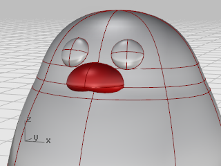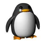
Rendered with Penguin renderer by Jari Saarinen.
This tutorial demonstrates point-editing techniques including moving and scaling control points and adding knots to surfaces to increase control. In addition, you will use blends to create smooth transitions between surfaces.
You will learn how to:
| ● | Rebuild surfaces to add additional control points. |
| ● | Insert knots in a surface to add control points in a specific location. |
| ● | Edit surface control points to define a shape. |
| ● | Scale control points to change the object shape. |
| ● | Use object snaps projected to the construction plane. |
| ● | Orient an object on a surface. |
| ● | Create smooth blends between surfaces.
|
If you like, open the example model, Penguin.3dm, and try to match the shapes as you are building the model. Experiment with your own shapes, too.
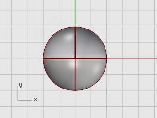
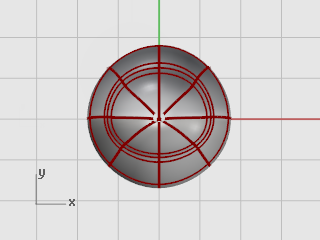
The body and head are created from one sphere. The shape is formed by moving the control points in the sphere to create the head.
![]() Draw a sphere
Draw a sphere
| 4 | In the Top viewport, use the Sphere command to draw a sphere with a radius of 10 units.
|
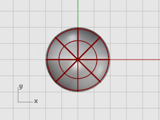
![]() Rebuild the sphere
Rebuild the sphere
| 4 | Use the Rebuild command to add more control points to the sphere. In the Rebuild Surface dialog box, set the Point count in the U and V directions to 8 and the Degree in the U and V directions to 3. Check Delete input. Click OK.
|
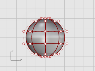
![]() Turn control points on
Turn control points on
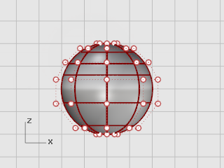
| 4 | Use the PointsOn (F10) command to turn on the sphere’s control points. Look in all the viewports at the structure of the control points. The next step will change this structure so the influence of moving the control points does not extend over the whole sphere.
|
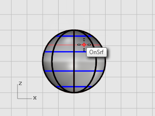
![]() Insert knots
Insert knots
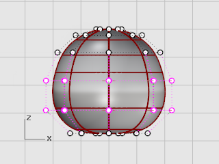
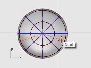
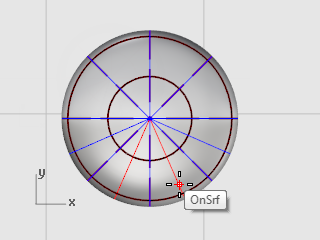
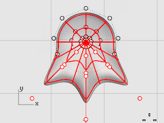
| 4 | Use the InsertKnot command to insert two knots in the sphere in the area where you want the neck. Insert the knots in the u-direction only as illustrated.
Examine the control point structure after inserting the knot.
Reposition control points to create the indentation for the neck and to reform the body shape. |
![]() Flatten the bottom
Flatten the bottom
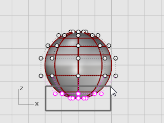
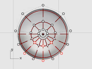
| 1. | In the Front viewport, select all the control points in the lowest rows of the sphere.
Use the SetPt command to match them to the bottom pole point in the world z-direction only. |
| 2. | In the Set Points dialog box, check Set Z, clear the Set X and Set Y check boxes, and click World. |
| 3. | Drag the selected control points up.
This will align all of the selected control points to the same z-value (up in Front viewport), flattening the surface.
|
![]() Drag points
Drag points
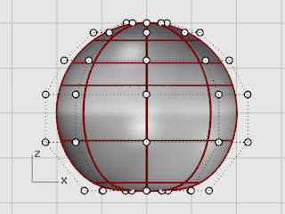
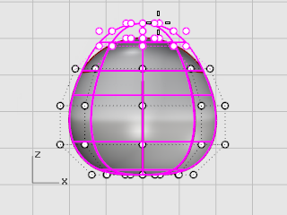
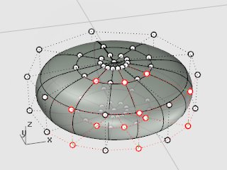
| 4 | Select rows of control points with a window and drag them up or down in the Front viewport to shape the body.
Use WireFrame display mode if you find it easier to select control points in wireframe views.
|
![]() Scale points
Scale points
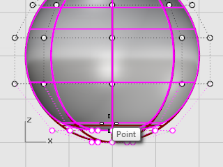
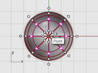
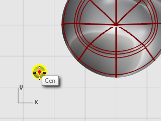
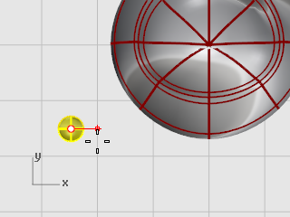
| 1. | Select rows of control points with a window in the Front viewport. |
| 2. | In the Top viewport, use the Scale2D command to move them closer or farther away from the central point. To pick the base point for the Scale2D command use the Point object snap with Project turned on. This will scale the points parallel to the construction plane. Watch the Front viewport to see the changes in the body shape as you move the control points closer to and farther from the center.
Experiment with the Project setting in the Osnap panel to see how it works. You will be able to see the tracking line projected to the construction plane in the viewports. Match the example model or use your own shape.
|
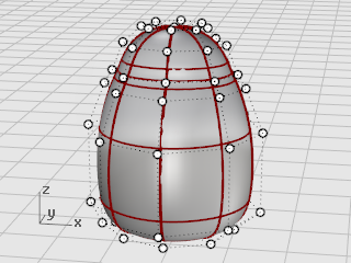
| 3. | Drag individual groups of control points to make the body slightly flatter in the front near the neck as illustrated.
|
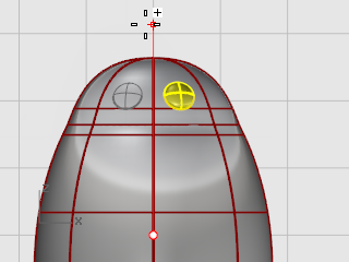
The eye is an ellipsoid shape that is oriented onto the surface.
![]() Create the eye
Create the eye
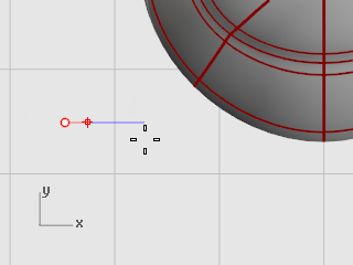
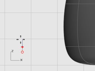
| 1. | In the Top viewport, start the Ellipsoid command. Place the center point anywhere. |
| 2. | At the End of first axis prompt, type 1.1 to constrain the distance from the center point to the end of the axis to 1.1 units. Drag the cursor to the right and pick.
|
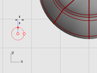
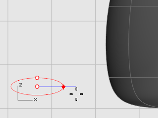
| 3. | At the End of second axis prompt, type 1.1 to constrain the distance. Using these constraints has created a circular ellipsoid when seen from the top. Drag the cursor up or down in the Top viewport and pick.
|
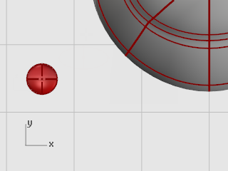
| 4. | At the End of third axis prompt, type .5, press Enter.
|
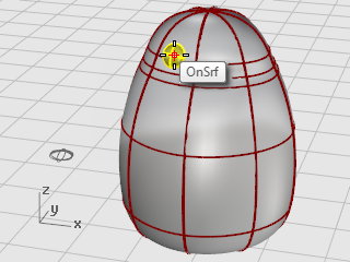
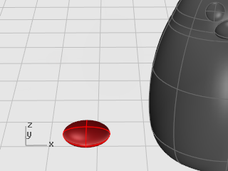
![]() Orient the eye on the surface
Orient the eye on the surface
| 1. | Select the eye ellipsoid in the Top or Perspective viewport. |
| 2. | Start the OrientOnSrf command. |
| 3. | At the Base point... prompt, in the Top viewport, pick the center of the ellipsoid.
|
| 4. | At the Reference point for scaling and rotation prompt, pick any point to the right or left of the eye ellipsoid. The exact location is not important.
|
| 5. | At the Surface to orient on prompt, select the penguin body/head. |
| 6. | In the Orient on Surface dialog box, click OK. |
| 7. | At the Point on surface to orient to… prompt, move the cursor onto the head to where you want to place the eye and click.
|
![]() Mirror the eye
Mirror the eye
| 4 | Use the Mirror command in the Front viewport to create the second eye.
|
The beak is another ellipsoid that you can edit to change the shape.
![]() Create the basic beak shape
Create the basic beak shape
| 1. | In the Top viewport, start the Ellipsoid command. Place the center point anywhere. |
| 2. | At the End of first axis prompt, type 3 to constrain the distance from the center point to the end of the axis to three units. Drag the cursor to the right and pick.
|
| 3. | At the End of second axis prompt, type 2 to constrain the distance. Using these constraints creates a circular ellipsoid when seen from the top. Drag the cursor up or down in the Top viewport and pick.
|
| 4. | At the End of third axis prompt, type 1, press Enter.
|
![]() Shape the beak
Shape the beak
| 1. | Turn on the beak's control points (F10). In the Front viewport, select the lower row of points and drag them up.
|
| 2. | Select the row of points in the top center and drag them down to shape the beak. Try using the Nudge keys (Alt + Arrow direction keys) to nudge the selected points.
|
![]() Move the beak
Move the beak
| 4 | Move the beak into position.
|
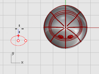
The feet are created using another ellipsoid. Knots are added to help create the webbed toes.
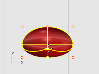
![]() Draw the beginning ellipsoid
Draw the beginning ellipsoid
| 1. | In the Front viewport, start the Ellipsoid command. Place the center point anywhere. |
| 2. | At the End of first axis prompt, type 1 to constrain the distance from the center point to the end of the axis to one unit. Drag the cursor up and pick.
|
| 3. | At the End of second axis prompt, type 3 to constrain the distance. In the Top viewport, drag the cursor up and pick.
|
| 4. | At the End of third axis prompt, type 3, press Enter.
|
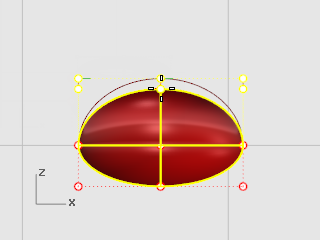
![]() Rebuild the ellipsoid
Rebuild the ellipsoid
| 4 | Use the Rebuild command to add more control points to the ellipsoid. In the Rebuild Surface dialog box, set the Point count in the U and V directions to 8 and the Degree in the U and V directions to 3. Check Delete input. |
![]() Insert knots to create the webbed feet
Insert knots to create the webbed feet
| 4 | Use the InsertKnot command to insert four knots in the ellipsoid as illustrated.
Set the Symmetrical=On. Insert the knots in the V-direction.
|
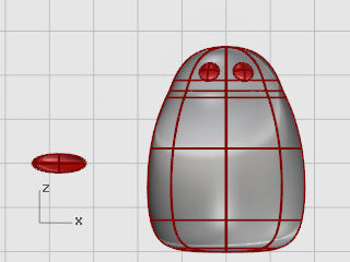
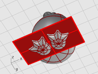
![]() Scale the points from the center
Scale the points from the center
| 1. | Select control points as illustrated.
Use window and crossing selections to select the control points on both the top and bottom of the ellipsoid.
|
| 2. | Use the Scale2D command to scale the control points out from the center of the foot. Use the Point object snap to set the base point of the scale to the center point of the ellipsoid. Drag the points to make the whole foot about twice the size of the original ellipsoid.
|
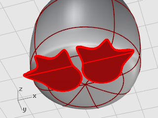
![]() Move the foot into position
Move the foot into position
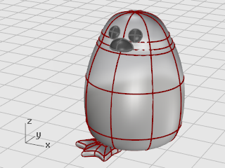
| 4 | Use the Move command to move the foot under the penguin body. |
![]() Rotate the foot out
Rotate the foot out
| 4 | Use the Rotate command to rotate the foot out slightly.
|
![]() Mirror the foot
Mirror the foot
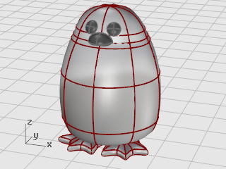
| 4 | Use the Mirror command to create the second foot.
|
![]() Create a cutting plane
Create a cutting plane
| 1. | Select the feet. |
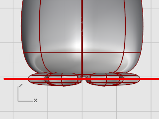
| 2. | In the Front viewport, use the CutPlane command to make a planar surface that passes through the feet as illustrated.
The CutPlane command makes a plane that passes through the selected surfaces along the line you draw.
|
![]() Trim and
Trim and ![]() Join the feet and the plane
Join the feet and the plane
| 1. | Trim the bottoms of the feet off with the plane as the cutting object. |
| 2. | Trim the excess plane from outside the feet. |
| 3. | Join the plane parts and the feet.
|
The tail is another ellipsoid. It is joined to the body with a smooth blend surface.
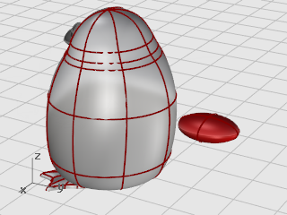
![]() Create the tail shape
Create the tail shape
| 4 | Draw an Ellipsoid that is 4 units long, 3 units wide (Top viewport), and 1.5 units tall (Front viewport).
|
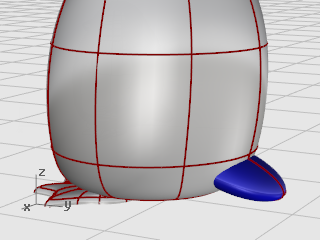
![]() Union the tail and body
Union the tail and body
| 4 | Use the BooleanUnion command to trim and join the tail and the body shapes. The transition between the tail and body is rather abrupt; so replace this with a smooth blend surface. To do this, you must first create a gap between the two parts for the blend surface to fill. |
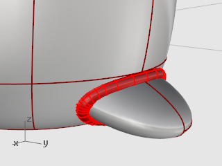
![]() Pipe the intersection
Pipe the intersection
| 4 | Use the Pipe command to create a circular surface around the edge between the body and tail. At the Select curve to create pipe around prompt, select the edge between the tail and the body. At the Radius for closed pipe prompt, type .4.
|
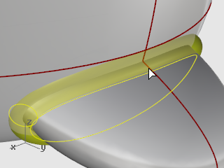
![]() Trim the body and tail with the pipe
Trim the body and tail with the pipe
| 1. | Use the Trim command to trim both the body and the tail surfaces inside the pipe. |
| 2. | At the Select cutting objects prompt, select the pipe, and press Enter.
|
| 3. | At the Select object to trim prompt, select the body/tail, and press Enter. Tip: Pick on the isocurve or edge that you can see inside the pipe.
|
With the SetObjectDisplayMode command, set the pipe to a wireframe or ghosted display mode so you can see the edge between the body and the tail.
If you select the wrong part, undo within the Trim command and try again.
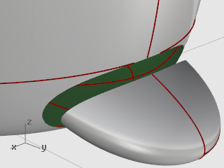
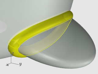
![]() Blend between the tail and body
Blend between the tail and body
| 4 | Use the BlendSrf command to create a smooth surface between the tail and the body.
|
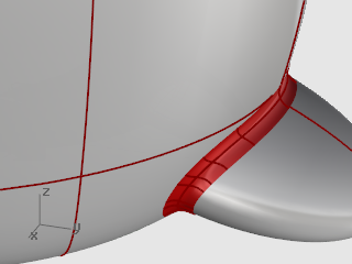
![]() Join the body and tail
Join the body and tail
| 4 | Join the blend and tail to the body |
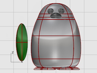
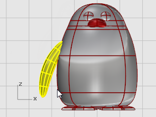
![]() Create the base wing shape
Create the base wing shape
| 4 | Draw an Ellipsoid that is 2 units long, 2 units wide (Top viewport), and 6.5 units tall (Front viewport).
|
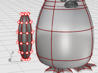
![]() Rebuild the wing
Rebuild the wing
| 1. | Use the Rebuild command to add more control points to the ellipsoid. In the Rebuild Surface dialog box, set the Point count in the U and V directions to 8 and the Degree in the U and V directions to 3. Check Delete input.
|
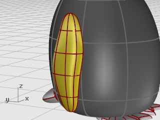
| 2. | Drag control points to create the shape.
|
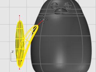
![]() Bend the wing to the body
Bend the wing to the body
| 1. | Use the Bend command in the Front viewport to bend the top of the wing shape toward the body. At the Start of spine prompt, in the Front viewport, pick near the bottom of the wing. At the End of spine prompt, pick near the top of the wing. At the Point to bend through… prompt, drag the top of the wing toward the body.
|
| 2. | If further positioning is needed, use the Rotate and Move commands to place the wing.
|
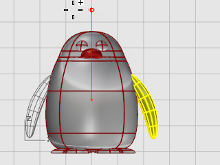
![]() Mirror to the other side
Mirror to the other side
| 4 | Use the Mirror command to create the opposite wing.
|
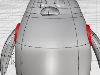
![]() Boolean Union the wings and the body
Boolean Union the wings and the body
| 4 | To trim the wing holes and the wing, select both wings and the body and use the BooleanUnion command. |
![]() Pipe the intersection
Pipe the intersection
| 4 | Use the Pipe command to create a circular surface around the edge between the body and each wing. At the Select curve to create pipe around prompt, select the edge of the hole in the body or the edge of the wing surface. At the Radius for closed pipe prompt, use a radius of about .6.
|
![]() Trim the body and wing
Trim the body and wing
| 1. | Use the Trim command to trim the body and wing surfaces inside the pipe surfaces. |
| 2. | Delete the pipe surfaces.
|
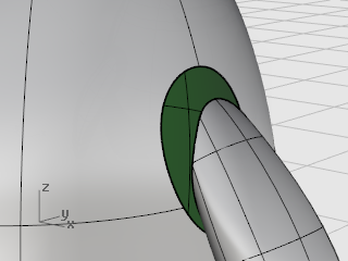
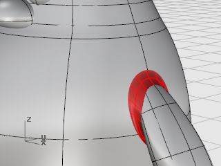
![]() Blend between the body and wings
Blend between the body and wings
| 4 | Use the BlendSrf command to create a smooth surface between each wing and the body.
|
![]() Join the body and wings
Join the body and wings
| 4 | Join the blends and wings to the body |
To finish the penguin, split the front part of the body so a different material can be applied to it.
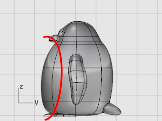
![]() Draw a trim curve
Draw a trim curve
| 4 | In the Right viewport, draw a Curve from the beak down to the bottom as illustrated.
|
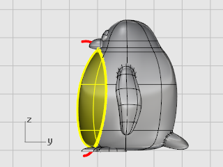
![]() Split the body with the curve
Split the body with the curve
| 4 | Use the Split command to split the body surface with the curve.
This allows a different color for the front of the body. |
![]() Join the body parts
Join the body parts
| 4 | Use the Join command to join the body (except the front), the tail, and the wings.
|
Rendering creates a realistic picture of your model with colors you assign. These render colors are different from the layer colors you might be using, which control the display in wireframe and shaded modes.
![]() Set up the view
Set up the view
| 4 | Use the Rendered display mode to set the viewport rendered mode. |
![]() Assign materials
Assign materials
| 1. | Select the body. |
| 2. | Start the Properties command. |
| 3. | In the Properties window, click the Material icon. |
| 4. | Set Assign material by, to Object. |
| 5. | Under Basic Settings, click the Color swatch. |
| 6. | In the Select Color dialog box, select a color for the body. |
| 7. | Set the Gloss finish to about 40. |
| 8. | Select the other parts and apply materials in the same way.
|