Rhino offers aids to organizing your work:
| ● | Layers |
| ● | Groups |
| ● | Blocks |
Each method offers a different approach to model organization. Using layers lets you assign a layer designation to objects. Groups associate objects so they can be selected as one. Blocks let you store and update an association of objects. Worksessions let you work on a part of a project while using other models in the project as references.
Rhino also provides the ability to add notation to your model. These appear as objects in the model.
| ● | Dimensions |
| ● | Leaders |
| ● | Text blocks |
A different form of notation always displays facing towards the view plane.
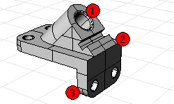
| ● | Annotation dots |
| ● | Arrowheads |
In addition, you can add Notes to the model. Notes do not appear in the model, but display in a separate window.
Layers are a way of grouping objects and applying certain characteristics to all objects that have that layer assignment. There are two “mental models” you can use when you think of layers—they can be thought of either as a “storage location” for the objects or as a way to assign a set of characteristics or properties to objects.
Layer states include a layer name, the color used to display the objects, and the on/off and locked/unlocked status of all the objects on a layer. Objects on layers that are off are not visible in the model. Objects on locked layers cannot be selected but can be snapped to. Objects are always created on the current layer. This layer assignment can be changed later.
To accomplish the most common tasks related to layers, click the Layer pane in the status bar to display the popup layer list. You can set the current layer; change the on/off, locked/unlocked state; and the layer color. In addition, right-click the layer name to create a new layer, rename a layer, delete the selected layer, select objects on the selected layer, change objects to the selected layer, and copy objects to the selected layer.
Accomplish more detailed layer management with the Layers panel. Right-click the Layer pane to open the Layers panel. The Layers panel sets the current layer, locks and unlocks layers, turns layers on and off, changes the layer color and sets the layer render material. You can create new layers, delete layers, move layers up or down in the layer list, filter the layer list, set the current layer to match an object in the model, change objects to a selected layer, select all layers, and invert the selection.
The SelLayer command selects all objects on a layer.
A group is a collection of objects that select as one for moving, copying, rotating, or other transforms and applying properties such as object color. Grouping objects assigns a group name to each object that is displayed as a part of its properties. Objects with the same group name belong to the same group.
| ● | Group groups objects for selection. A group can contain one or more sub-groups. |
| ● | Ungroup destroys the group. |
| ● | SetGroupName changes the name assigned by default. Naming different groups to the same name combines those groups into one. |
| ● | AddToGroup and RemoveFromGroup add and remove objects from groups. |
| ● | SelGroup selects groups by name. |
A block is another way of associating objects together to form a single object. The Block command creates a block definition in the current model. The Insert command places instances of this block definition in your model. You can scale, copy, rotate, array, and otherwise transform block instances in the model. If you edit the block definition, all instances of the block are changed to this new definition. Blocks can streamline modeling, reduce model size, and promote standardization of parts and details.
Multiple instances of a block can be located, scaled, and rotated into a model with the Insert command. Block definitions are created with the Block or Insert command. Materials and other object properties on block instances are determined by the component objects.
Exploding a block instance places the block geometry using the instance location, scale, and rotation.
To redefine a block, Explode the block, edit the geometry, and then re-create the block with the same insertion point and name.
The BlockManager command displays a dialog box that lists all the block definitions in the model. Use the Block Manager dialog box to view block properties, export a block definition to a file, delete a block definition and all its instances, update a block definition from a file, find out what blocks are nested in other blocks, and count the number of block instances in the model.
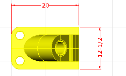
You can dimension objects in your model, with your choice of font, units display, decimal precision, text and arrow size, and text alignment. After dimensions are placed, you can select all dimensions, edit dimension text, turn control points on to move dimension elements, and delete dimensions. You can place horizontal, vertical, aligned, rotated, radial, diameter, and angle dimensions, text blocks, leaders, and create a 2-D hidden line drawing.
Dimensions are not associative. Changing your geometry will not update the dimension unless the dimension was drawn with history enabled. Changing the dimension will not update your geometry.
The Dim command places horizontal and vertical dimensions depending on the direction you pick the points.
Dimensions are created using the current dimension style. Create new dimension styles to control text size and font, and other dimension properties. Use the settings in the Document Properties window to create new styles and set the properties of existing styles.
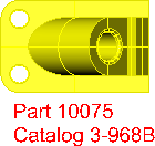
The Text command places annotation text in your model.
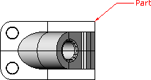
The Leader command draws an arrow leader.
The Dot command places a text dot.
Dots are always parallel to the view. Dots are displayed in the layer color. Dot size is constant on the screen. As you zoom in and out, the dot displays the same size.
The Make2D command creates curves from the selected objects as silhouettes relative to the active view. The silhouette curves are projected flat and then placed on the world x,y‑plane.
The command options create the 2‑D drawing from the current view, current construction plane, create a four-view layout using US or European projection angles, set layers for the hidden lines, and display tangent edges.
The Notes command provides a means of storing text information in your model file. You can type information directly into the Notes text box. If you leave the Notes box displayed when you close the model file, it will display the next time the file is opened.