![]()
File
Settings
| Toolbar | Menu |
|---|---|
|
|
File Settings |
The Render Document Properties page and the Rendering panel manage the Rhino Render settings for the current model.
The basic renderer supports spot, point, directional, rectangular, and linear lights.
This information is also displayed as a panel.
Renders the active viewport the active viewport using the pixel size of the viewport.
Renders the active viewport using the custom resolution. Type the custom width and height resolution in pixels.
Calculates the size of the image in the selected unit system based on the Resolution and DPI settings. This is useful for determining the size of the image for printing.
Set the image size in pixels, inches, millimeters, or centimeters.
Image pixels ("dots") per inch.
A method of smoothing the jagged edges along the lines and curves of text or graphics. This is done by a mathematical process that super samples pixels. Aliasing is caused by limited display resolution. Aliasing effects include stair-stepping along diagonal lines and moiré effects in checkerboards. Rhino calculates each pixel in the rendered image by averaging several samples taken from the pixel area. This makes the image appear smoother, but also slows down rendering.
Sets the color of the darkest spot on the objects in the scene in the rendered image. The color of the low light areas of the model is a blend of the object color and the ambient light color.
Sets a different color for the lower area.
Turns usage of the Bottom color setting on.
The background is what you see directly in front of the camera if there are no objects in the way. The background is not 3‑D — it exists only on the screen.
Displays a solid color.

Displays a two-color gradient.
Displays the portion of the current environment that the camera sees in the viewport.
Sets the projection style for the environment.
Uses information in the image to determine the mapping.
Elliptical subsection reaching each border of the texture is mapped onto the sphere. This projection is the result of taking a photo of a mirror sphere with an orthographic camera.
Maps the entire texture onto all sides of the cube.
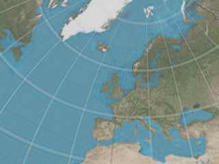
Also known as angular fish-eye projection or azimuthal equidistant projection. Elliptical subsection reaching each border of the texture is mapped onto the sphere.
See: Wikipedia: Azimuthal equidistant projection.
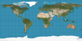
Also known as equirectangular projection. Horizontal line in the middle of the texture is mapped to the equator of the sphere.
See: Wikipedia: Equirectangular projection.
Subsections corresponding to each side of the cube are located side by side dividing the texture into six equal parts.
See: Wikipedia: Cube mapping.
Maps texture directly to background. Environment looks always the same no matter where the camera is looking.
Like spherical projection but the entire texture is mapped onto the upper half of the sphere. The bottom border of the texture is stretched over the under side of the sphere.
Subsections corresponding to each side of the cube are located in a vertical cross pattern. Each subsection is one fourth of the image in height and one third in width.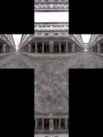
Subsections corresponding to each side of the cube are located in a horizontal cross pattern. Each subsection is one third of the image in height and one fourth in width.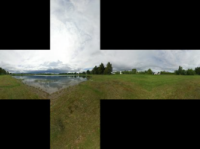
Displays the current viewport wallpaper.
Fits the wallpaper to the rendered view.
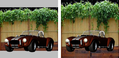
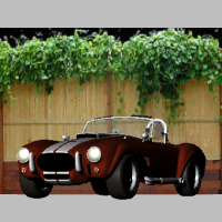
The background is rendered with an alpha channel for transparency. The image must be saved to a file format that supports alpha channel transparency (.png, .tga, .tif).
![]()
Turns on skylight.

Sets an environment that is used as sky lighting.
Sets the projection style for the environment.
Uses information in the image to determine the mapping.
Elliptical subsection reaching each border of the texture is mapped onto the sphere. This projection is the result of taking a photo of a mirror sphere with an orthographic camera.
Maps the entire texture onto all sides of the cube.
Also known as angular fish-eye projection or azimuthal equidistant projection. Elliptical subsection reaching each border of the texture is mapped onto the sphere.
See: Wikipedia: Azimuthal equidistant projection.
Also known as equirectangular projection. Horizontal line in the middle of the texture is mapped to the equator of the sphere.
See: Wikipedia: Equirectangular projection.
Subsections corresponding to each side of the cube are located side by side dividing the texture into six equal parts.
See: Wikipedia: Cube mapping.
Maps texture directly to background. Environment looks always the same no matter where the camera is looking.
Like spherical projection but the entire texture is mapped onto the upper half of the sphere. The bottom border of the texture is stretched over the under side of the sphere.
Subsections corresponding to each side of the cube are located in a vertical cross pattern. Each subsection is one fourth of the image in height and one third in width.
Subsections corresponding to each side of the cube are located in a horizontal cross pattern. Each subsection is one third of the image in height and one fourth in width.
Controls whether or not spotlights that are on hidden layers or that are hidden with the Hide command are rendered.
Curve objects are rendered with the surfaces.
Surface isoparametric curves and edges are rendered with the surfaces.
Dimensions and texts are rendered with the surfaces.
The width and height of each grid cell in pixels.
The smaller the grid cell size, the more memory it takes and the more memory it takes to build, but the faster the final render.
The shadow ray is the ray shot from the scene towards each light when the intersection between the eye ray and the scene is found. Usually the lions share of the render time is spent tracing the shadow rays.
To increase calculation speed for the spotlight shadow rays, the render plug-in divides the spotlight cone into rectangular regions, and again builds a sorted list of the objects within each region. This speed increase only applies to spotlights, because they are very similar to the viewports, the light location is like the camera location, and the light cone defines the viewport.
The spotlight grid is defined in number of grid cells instead of pixels, because there is no pixel size associated with lights.
Prevents self-shadowing artifacts. When the intersection between the eye ray and the scene is found, the intersection point is moved (offset) towards each light before calculating the shadow ray. The reason is there's always some numerical fuzz in calculating the intersections, and if the point is not offset, the shadow ray might hit the very same polygon again, putting shadows in wrong places. You can see the self shadowing artifacts if you set the setting to zero, and then render the scene.
The amount of offset.
A binary space partitioning (BSP) tree is another way to increase rendering speed. Instead of testing each polygon one-by-one, the objects and polygons are divided into a tree-like hierarchy based on the location in space.
The renderer builds multiple trees, one that contains the whole object bounding boxes, and one per object that contains the polygons for that object.
The BSP tree takes some time to build and takes some memory. A deeper tree may take longer to build, but may renders faster. A shallow tree is faster to build, but may take a long time to render.
Controls how many times the scene can be subdivided when building the tree.
The tree depth defaults to Auto, and node size to 1. There should be no need to change these settings unless you render a scene that is so huge that Rhino runs out of memory using the default settings.
Defines the optimal size for each node that contains the objects or polygons.
The transparency bounces setting controls how many times rays that hit transparent objects are traced: 12 means a stack of 12 transparent sheets will render properly, but the 13th sheet will render opaque. To keep the render times reasonable, the limit is 15.
The reflectivity bounces setting controls how many times rays that hit reflective objects are traced. To keep the render times reasonable, the limit is 15.
These settings control the slow but more accurate focal blur that is generated by shooting more rays into the scene.
Adjusts the focal distance and aperture automatically so that selected objects are rendered sharp.
The distance to a plane perpendicular to the camera that should be in focus.
The 35 mm single-lens-reflex camera equivalent aperture.
The number of rays per sub-pixel that is generated for the effect. The higher the count the more accurate and smoother the result, and the longer it takes to render.
The amount of radial noise added to the ray origins. Bigger jitter makes the image noisier, but also hides the steps in shading caused by combining the image from multiple samples.
Render the objects using the current renderer.
Rhino for Mac © 2010-2017 Robert McNeel & Associates. 24-Oct-2017