ExtrudeMesh
|
Toolbar |
Menu |
|---|---|
|
|
Mesh Edit Tools > Extrude Faces and Boundary Edges |
The ExtrudeMesh command extrudes mesh faces and boundary edges with different direction modes.
Steps
-
Start the command.
-
Select mesh faces or boundary edges to extrude.
To extrude a whole mesh, select the mesh before starting the command.
-
Set command-line options.
-
Pick or enter the extrusion distance.
Command-line options
EdgeLoop
Pick an edge on the boundary to select an edge loop.
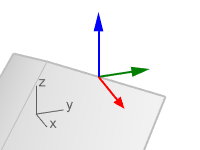
Basis
WCS
All faces or boundary edges extrude in the same direction based on world coordinates.
Direction
Free
The direction is picked freely.
X/Y/Z
The direction is fixed to the world X, Y, or Z axis.
UVN
Each face or edge extrudes in the direction based on UVN coordinates.
Direction
Free
The direction is picked freely.
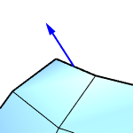
V (Boundary edges only)
Boundary edges extrude along the extending direction of the faces.
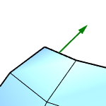
N
Faces extrude along vertex normal directions.
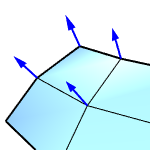
Boundary edges extrude perpendicular to the faces.
SetBasePoint
Picks a point as the starting point of the extruding distance.
-
Pre-select a mesh to extrude the whole mesh.
See also
ExtrudeSubD
Extrudes SubD faces and boundary edges with different direction modes.
ExtrudeSrf
Drive surface edges in a straight line to create a solid.
ExtrudeCrv
Drive closed planar curves in a straight line.