8 - Transforms - Move, Copy, Rotate, and Scale
Transforms change the location, rotation, number and shape of whole objects by moving, mirroring, arraying, rotating, scaling, shearing, twisting, bending, and tapering. The transform commands do not break the objects into pieces or cut holes in them.
Note: For all of the following exercises, the images were captured using Shaded mode display.
Move
Use the Move command when you want to move an object a certain distance or if you want to use object snaps to place an object accurately.
You can pick these locations on the screen or type coordinates at the command prompt.
 Practice moving objects
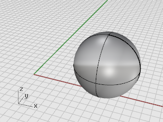
The object of this exercise is to move a sphere from the center of the sphere to the coordinate system origin at 0,0,0.
The Move command requires a from and to location.
-
Start a new model.
-
Draw a Sphere anywhere on the screen.
-
Select the sphere.
-
On the Transform menu, click Move.
Optional: Press F1 to review the Help topic for the Move command.
-
At the Point to move from prompt, with the Center (Cen) object snap on, move the mouse around the edge of the sphere until the Cen tooltip displays and click.

-
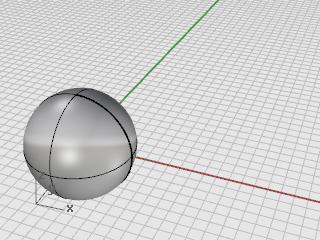
At the Point to move to prompt, type 0,0,0.
The center of the sphere moves to the 0,0,0 coordinate point.
Tip: Simply typing 0 is a shortcut for the coordinates 0,0,0.
Move objects by dragging
The quickest way to move objects is to click the object and drag it. Rhino provides tools for accuately dragging objects. You can drag objects in any viewport. Object snaps help align objects to each other.
 Practice dragging objects
-
Open the tutorial model Drag Objects.3dm.
(Help menu > Learn Rhino > Tutorials and Samples > User's Guide > Drag Objects)
-
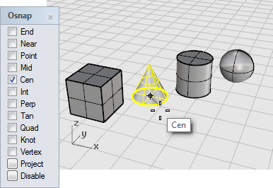
In the Osnap control, turn on the Center (Cen) object snap.
-
In the Perspective viewport, move the mouse cursor close to the cone's bottom edge, hold down the left mouse button until the Cen object snap tooltip displays.
-
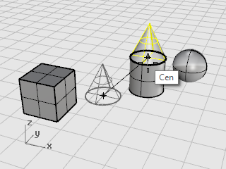
Drag the cone to the top edge of the cylinder, the Cen object snap tooltip displays.
-
Release the mouse button to place the cone.
Note: Dragging with accuracy like this can be tricky. Keep your eye on the object snap tooltips.
Move objects using elevator mode
You can press the Ctrl key to move objects in the z‑direction. This is called elevator mode. See Chapter 5, Accurate Modeling, Elevator mode.
Elevator mode is similar to Ortho, except the movement is vertical to the active construction plane.
To practice using elevator mode to move vertically, you are going to move the box to a location five units above the center of the sphere.
Using elevator mode to move objects vertically lets you work in the Perspective viewport more often.
Move the box with reference to another object
Note: For the following images, the Display Mode Shade-highlight selected surfaces and polysurfaces option has been turned on.
(Tools menu > Options > View > Display Modes > Shaded > Objects > Selection)
-
Turn Ortho off.
-
On the Transform menu, click Move.
-
In the Perspective viewport, rotate the view so the sphere is toward the front.
-
Select the box.

-
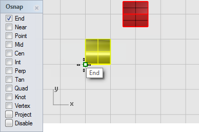
At the Point to move from... prompt, turn on the End object snap and click the lower right corner of the box.
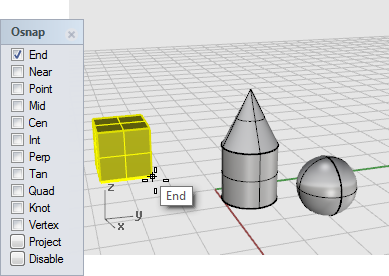
-
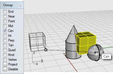
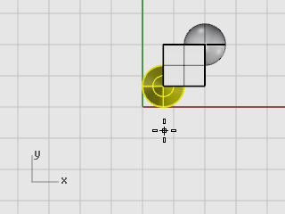
At the Point to move to prompt, turn on the Cen object snap.
Drag the box around the equator of the sphere until the Cen tooltip displays.
-
Hold down the Ctrl key, and click at the center of the sphere.
-
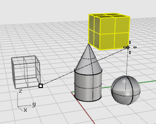
Release the mouse button and the Ctrl key, and start to drag the box.
The box can now move only up and down in the z‑direction.
-
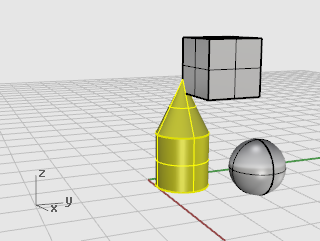
At the command prompt, type 5, and press Enter.
The box will be placed so that the selected end of the box is 5 units in the z‑direction from the center of the sphere.
Copy objects
The Copy command makes copies of objects. Like the Move command, the Copy command requires a from and to location.
 Practice copying objects
-
On the Transform menu, click Copy.
Optional: Press F1 to review the Help topic for the Copy command.
-
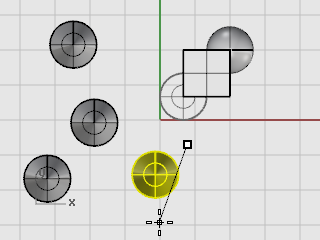
In the Perspective viewport, select the cone and the cylinder.
-
At the Point to copy from... prompt, click anywhere in the Top viewport.
-
At the Point to copy to... prompts, click where you want the copies.
-
When you have enough copies, press Enter or right-click the mouse to end the command.
Rotate
The Rotate command rotates an object around a center point.
 Rotate an object
-
Open the tutorial model Rotate-Scale.3dm.
(Help menu > Learn Rhino > Tutorials and Samples > User's Guide > Rotate-Scale)
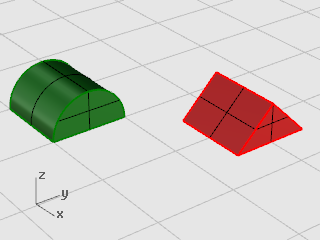
-
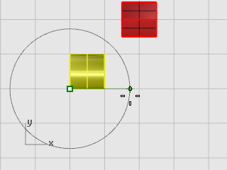
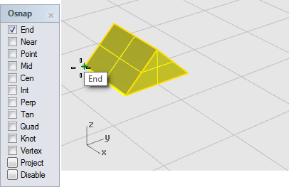
Select the green half-cylinder as shown in the illustration below.
-
On the Transform menu, click Rotate.
Optional: Press F1 to review the Help topic for the Rotate command.
-
in the Top viewport at the Center of rotation... prompt, with the End object snap on, click the lower left corner of the half-cylinder as shown in the illustration below.
-
In the status bar turn Ortho on.
-
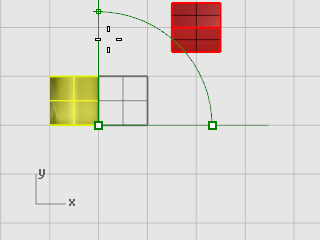
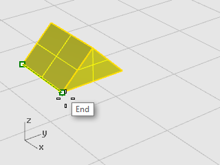
At the Angle or first reference point... prompt, drag the cursor to the right as shown in the illustration below, and click.
This establishes the base angle for the rotation.
-
At the Second reference point... prompt, drag the cursor up as shown in the illustration below, and click.
The half cylinder rotates 90 degrees counter-clockwise.
Scale
The Scale commands give you control over the direction of the scale. You can re-size objects uniformly in one, two, or three directions, or scale an object with a different scale factor in each direction.
 Scale the prism
-
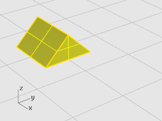
In the same Rotate-Scale model, select the red prism shape.
-
On the Transform menu, click Scale, and then click Scale 3‑D.
Optional: Press F1 to review the Help topic for the Scale command.
-
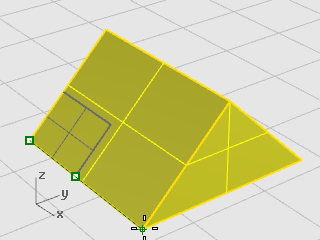
At the Base point... prompt, with the End object snap on, click the left corner of the prism as shown in the illustration below.
This sets the base point from which the object will grow or shrink.
Note: In this simple example, you will first show the object's original size by picking two points, a base point and a first reference point. Then you will show the object's new size by picking a second reference point.
-
At the Scale factor or first reference point... prompt, click the right corner of the prism as shown in the illustration below.
The distance between the base point and the first reference point sets the original size for the scale operation.
-
At the Second reference point... prompt, drag the cursor to the right.
The object grows as you drag the cursor.
-
Click to set the new object size as shown in the illustration below.
Enter a number to set the scale factor
- To make the object twice its original size, at the Scale factor... prompt, type 2.
- To make the object half its original size, at the Scale factor...prompt, type .5.
Scale an object to a specific size
- To make the prism in this example 2.35 units along the original side, at the Second reference point... prompt, type 2.35.
Mirror
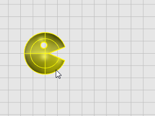
In this exercise, you are going to practice another basic editing command: Mirror. The Mirror command makes a reverse-image copy of the object. Objects are mirrored across a line that you draw in a viewport.
 Mirror an object
-
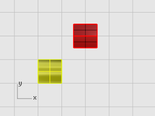
Open the tutorial model Mirror Objects.3dm.
(Help menu > Learn Rhino > Tutorials and Samples > User's Guide > Mirror Objects)
-
On the Transform menu, click Mirror.
Optional: Press F1 to review the Help topic for the Mirror command.
-
On the status bar, turn Ortho on.
-
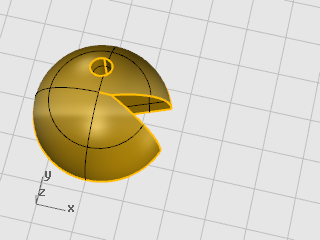
Select the object.
-
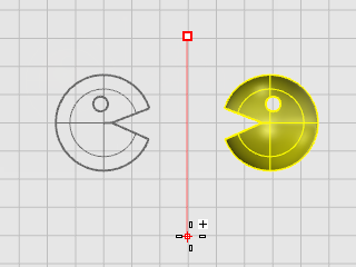
At the Start of mirror plane... prompt, in the Top viewport, click to the right of the face as shown in the illustration below.
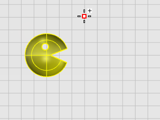
-
At the End of mirror plane... prompt, drag the cursor toward the bottom of the screen, and click to end the mirror line.
Rhino for Windows © 2010-2018 Robert McNeel & Associates. 24-Nov-2021
Open table of contents panel.