The cursor can always move freely, but sometimes you may need to put some restrictions on the cursor. You can restrict the cursor’s movement to the construction plane grid, a distance or an angle from a point, snap to specific locations on existing objects, or enter Cartesian coordinates to locate points in 2‑D or 3‑D space.
The Rhino cursor consists of a marker and a cross. The marker usually stays at the center of the cross. The cross always follows the mouse movement.
Rhino cursor (1), Marker (2) and Cross (3)
The marker may leave the cross when a constraint is in effect. For example, when Elevator mode is active, a tracking line connected to the marker displays. The location of the marker is picked when you click the left mouse button..
Grid snap constrains the marker to the crossing points of an imaginary grid that extends infinitely in the x‑ and y‑directions.
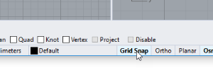
Click the Grid Snap pane on the status bar to turn grid snap on and off. Right-click the Grid Snap pane to set the snap spacing and other options.
Grid snap on (left); Grid snap off (right)
Ortho mode constrains the marker movement or object dragging to a specific set of angles. By default, this is parallel to the grid lines, but you can change this.
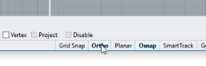
Click the Ortho pane on the status bar to turn ortho on and off.
Press and hold the Shift key to temporarily toggle the ortho mode.
Ortho off (left); Ortho 90° (center); Ortho 45° (right)
Ortho is active after the first point for a command. For example, after picking the first point for a line, the second point is constrained to the ortho angle.
Ortho off (left); Ortho on (right)
If you need a different angle for only a single operation, angle constraint is faster to use. Enter a specific angle for one operation instead of changing the ortho angle and then changing it back.
When Rhino asks you to pick a point, you can use object snaps to pick a precise location on an existing object. When you move the cursor near a location on an object that corresponds to an object snap, the marker jumps to that location.
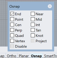
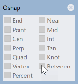
Object snaps are set in the Osnap control. The Osnap control is usually docked at the bottom of the screen, but it can be docked at other locations or floated. If the Osnap control is not open, click the Osnap pane in the status bar. When an object snap is checked, the text in the Osnap pane will change to bold.
A persistent object snap stays on until you turn it off. You can turn on as many persistent object snaps as you need.
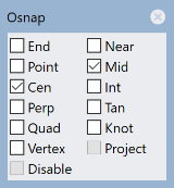
In the Osnap control, click object snap check boxes.
Multiple persistent object snaps may interfere with one another, so you can also turn on an object snap for a single pick. One-time object snaps override persistent object snaps. This lets you keep your persistent object snaps set, but to override them as needed with a one-time object snap.
Hold Shift and hover the mouse above the Osnap control. Click one of the gray check boxes.
-Or-
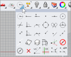
Select an object snap from the Object Snap toolbar.
-Or-
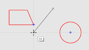
During a command, type an object snap name such as, cen (center), int (intersection), tan (tangent), and press Enter.
Object snaps normally take precedence over grid snap or other constraints. In some situations object snaps work in conjunction with other constraints. You will see examples of this later in this chapter. For more information, including video demonstrations, see the Rhino help topic Object snaps.
All persistent object snaps will be suspended, but remain their checking status.
All persistent object snaps will be cleared.
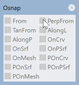
Some special object snaps let you select multiple reference points or add other advanced controls.
See the Rhino help topic Object snaps for more information about these object snaps.
Complex object snaps are also available from the Osnap control.
When entering points, you can restrict the cursor to a distance or angle from the previous point.
Ortho restricts the cursor movement to a 90-degree angle from the last point created.
Note: The default angle is 90 degrees, but any angle can be used. Right-click the Ortho pane for options.
Click the Ortho pane to toggle Ortho on and off while dragging the cursor.
You will see the cursor jump to 90 degrees when Ortho is on and drag freely when Ortho is off.
Note: A shortcut for toggling Ortho on and off temporarily is to hold down the Shift key.
The distance constraint restricts the distance the cursor can travel from the previous point. Set the distance constraint during a command by typing a number at the command prompt.
Drag the line around the first point until it heads the direction you want it to go, and pick a point for the end of the line.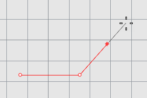
Angle constraint is similar to Ortho, but you can set any angle. The angle constraint setting is only in effect for the next pick.
Once you have set the angle, drag the line around the first point.
You will see that the marker jumps around the first point in 35-degree increments.
Distance and angle constraints can be used at the same time. The order you enter the distance and angle does not matter.
SmartTrack is a system of temporary reference lines and points drawn in the Rhino viewport using implicit relationships among 3‑D points, other geometry, and the coordinate axes directions.
Temporary infinite lines (tracking lines) and points (smart points) can be used by object snaps just like real lines and points.
You can snap to intersections of the tracking lines, perpendiculars, and directly to smart points as well as intersections of tracking lines and real curves. The tracking lines and smart points are displayed only for the duration of a command.
Rhino uses two coordinate systems: construction plane coordinates and world coordinates. Construction plane coordinates are defined for each viewport. World coordinates are fixed in 3‑D space.
For more information about coordinate systems, see www.mathopenref.com/coordinates.
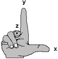
Coordinate systems follow what is called the right-hand rule. The right-hand rule can help you determine the direction of the z‑axis in a coordinate system. Form a right angle with the thumb and forefinger of your right hand. When your thumb points in the positive x‑direction, your forefinger points in the positive y‑direction, and the palm of your hand faces in the positive z‑direction.
Each viewport has its own construction plane. A construction plane is like a tabletop that the cursor moves on unless you use coordinate input, elevator mode, object snaps, or a few other instances where input is constrained. By default, each viewport’s construction plane is independent of those in other viewports.
Rhino’s standard viewports come with construction planes that correspond to the viewport. An exception is the default Perspective viewport, which uses the World Top construction plane, the same as the default Top viewport.
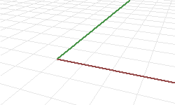
The grid helps you visualize the construction plane. The dark red line represents the construction plane positive x‑axis for that viewport. The dark green line represents the construction plane positive y‑axis for that viewport. The red and green lines meet at the construction plane origin (0,0) for that viewport.
Note: By default there is no line showing the construction plane z‑axis in order to cut down on clutter on the screen.
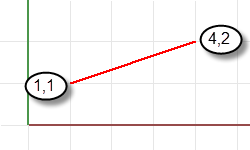
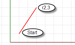
A line is drawn starting at 1 unit from the construction plane origin in the positive x‑direction and 1 unit from the construction plane origin in the positive y‑direction and ending at 4 units from the origin in the positive x‑direction and 2 units from the origin in the positive y‑direction.
You can also use 3‑D coordinates to place points that do not lie on the construction plane.
To use 3‑D coordinates, during a command, at a prompt requesting a point, type the coordinates in the format x,y,z where x is the x‑coordinate, y is the y‑coordinate, and z is the z‑coordinate of the point.
Use relative coordinates to locate points according to their relationship to the previous active point. Rhino remembers the last point used, so you can enter the next point relative to it. Relative coordinates are useful for entering a list of points where the relative locations instead of absolute locations of the points are known.
To enter relative coordinates, at a command prompt, type the coordinates in the format rx,y where r signifies that the coordinate is relative to the previous point.
Rhino contains one world coordinate system. The world coordinate system cannot be changed. When Rhino prompts you for a point, you can type coordinates in the world coordinate system in the format wx,y,z.
The arrow icon in the lower left corner of each viewport displays the direction of the world x‑, y‑, and z‑axes. The arrows move to show the orientation of the world axes when you rotate a view.

Elevator mode lets you pick points that are off the construction plane in the positive or negative z‑direction. Elevator mode requires two point picks to define the point. The first point sets the base point. The second specifies how far the final point is above or below the base point.
To move the marker in the construction plane z‑direction, hold the Ctrl key and click a point on the construction plane, and then drag vertically from the construction plane and click to pick a point.
Using elevator mode to move your pick point vertically from the construction plane lets you work in the Perspective viewport more easily.
Type Curve.
At the Start of Curve prompt, in the Perspective viewport, place the first point.
At the Next point of curve... prompt, pick a second point in the Perspective viewport.
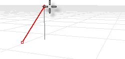
At the Next point... prompt, hold the Ctrl key and pick a point in the Perspective viewport.
This is the base point for the elevator mode action. After the base point is specified, the marker is constrained to a tracking line perpendicular to the construction plane that passes through the base point.
Drag the mouse in the Perspective viewport.
A tracking line displays indicating that the marker is constrained to move perpendicular to the construction plane.
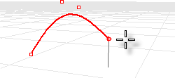
Pick a second point to specify the z‑coordinate of the desired point.
-Or-
Type a number to specify the height above the construction plane. Positive numbers are above the construction plane; negative numbers are below.
You can use other constraints such as coordinates, object snaps, or grid snap for the first point, and you can use object snaps for the height.
For more information about the mathematical principles involved in 3‑D modeling, see: www.mathopenref.com.
Rhino for Windows © 2010-2018 Robert McNeel & Associates. 24-Nov-2021