The BlendSrf command creates a blend surface between two surfaces.
With Record History on, the result can pay attention to changes in the input objects and have its own input settings changed using the Edit command line option.
Steps
| 1. | Select a surface edge. |
| 2. | Select adjacent edges or press Enter. |
| 3. | Select the edges to blend to and press Enter. |
| 4. | Select adjacent edges or press Enter. |
| 5. | Select and adjust control points or press Enter. |
Command-line options
ChainEdges
Selects surface edges that are touching the selected curve.
AutoChain
Selecting a curve or surface edge automatically selects all curve segments connected with the level of continuity set by the ChainContinuity option.
ChainContinuity
Controls the level of continuity required between segments to be selected with the AutoChain option.
Direction
Forward
Selects curves in the positive curve direction.
Backward
Selects curves in the negative curve direction.
Both
Selects curves in both the positive and negative curve direction.
GapTolerance
If the gap between two edges/curves is less than this value, the chain selection will ignore the gap and will select the next segment.
AngleTolerance
When Continuity is set to Tangency, if the angle between two edges/curves is less than this value, the chain selection will consider the criteria for continuity met and will select the next segment.
Options available after one chain segment is selected
Undo
Undo last segment selection.
Next
Select next segment.
All
Select all segments.
Keys for control
|
Shift By default the shape curves are separately edited at each end, Hold Shift to retain symmetry. With symmetry, point editing is mirrored to the other end of the curve. Alt Hold Alt while dragging the handles to change the angle between the shape curve and the surface edge.
|
|
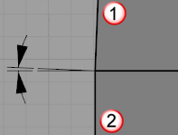
Drag seams to adjust (closed cross-section curves only)
| 1. | Select a seam point marker, and move it along the closed curve. |
| 2. | Continue to adjust the seam points until they line with each other and the closed curves all have the same direction, and then press Enter. |
Adjust seam options
Flip
Reverses the curve direction.
Automatic
Attempts to align the seam points and directions without intervention.
Natural
Moves the seam points to the way they were at the beginning of the command.
Adjust Surface Blend Options
![]() Lock
Lock
Check the Lock box to maintain the relationship between the two curve ends.
Sliders
Determine the distance of influence the surface has on the edge curve.
Sliders control each surface end (2).
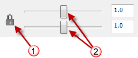
Lock sliders icon (1), surface end bulge controls (2).
Continuity Options
Sets the continuity for each surface end.
Position
Tangency
Curvature
G3
G4
AddShapes
Add additional curve profile shapes to increase control over the blend surface shape. This is especially important if the input shapes are complex and you want to control the shape in more locations.
Click a location on each surface edge to add another shape curve.
Note: When you snap to a point and add a shape, the command automatically creates a shape that connects to the corresponding point on the other side, which attempts to keep the blend simple.
Planar sections
Forces all shape curves to be planar and parallel to the specified direction.
Same height
If the gaps between the surfaces vary, this option maintains the height of the shape curves throughout the blend.
Preview
Check to dynamically display a preview as the options change.
Note
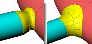
| ● | If you try to create a blend between a surface and a hole in another surface that is exactly the same size as the surface, Rhino will be forced to make the blend surface dip in quite a bit so it is smooth to both surfaces.
Hole the same size as surface (left). Hole larger than surface (right). |
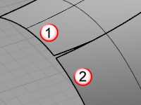
| ● | If the edges of two surfaces you are trying to blend share a corner intersection, the BlendSrf command will select all the contiguous edges as one. To choose the second edge separately, press Enter after choosing the first edge, then choose the edge of the second surface. |
| ● | Sometimes some holes appear in rendering between blend surfaces and their original surfaces appear in rendering. This is because the rendering was done with polygon mesh approximations of the true surfaces, so the meshes are not matching up exactly. |
| ● | Use the Join command to join them together into one object so the rendering and meshing won't have any cracks in it and will match up exactly. |
Tips
| ● | Always blend from the largest radius to the smallest radius across a model. |
| ● | Remove any edges you can prior to blending with MergeAllFaces or by way of surfacing in a simpler manner. Fewer intersected edges = Fewer problems as the blend rolls along any edges and tries to trim and join with the adjacent surfaces. |
| ● | Make sure there is enough room for the blend surface to trim and join with adjacent surfaces. The angle relationships between surfaces, sharpness of the bend in the edge around corners, and blend type all play a part in any particular case. |
See also
Fillet, blend, or chamfer between curves and surfaces
Rhinoceros 5 © 2010-2015 Robert McNeel & Associates. 17-Sep-2015