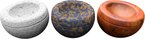
Materials can be created from images. Scan photographs and real materials like wallpaper and carpet, create patterns in a paint program, or use images from other sources of bitmap.
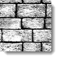
Imagine that the material stretches infinitely in all directions in space. The material becomes visible only where an object passes through it. Patterns are repeated infinitely (tiled) in four directions at a specified scale.
Small images that can be seamlessly tiled tend to work best. If the bitmap does not tile well, use the option to mirror the tiles. This guarantees matched edges.
Note: To make a bitmap image cover only part on the object (like a label on a wine bottle or a logo on a product), use the Decal feature instead.
Image maps can be used many ways. A common method is to use a picture of a real-world material as the materials color.
Note
Refresh the image definition
When a bitmap file is changed using an image editor such as Photoshop, you must refresh the bitmap definition in Flamingo nXt.
To refresh the bitmap
 On the Flamingo
nXt menu, click Utilities
> Clear bitmap cache.
On the Flamingo
nXt menu, click Utilities
> Clear bitmap cache.
Displays a preview of the selected image file.
Displays the resolution in pixels of the image file.
Image maps used in material definitions are always repeated (tiled). These settings specify how large each instance (tile) will be in current model units.
Sets the tile size.
 Lock
Lock
Maintains the ratio between the Width and Height.
Mirrors the map in both directions as it is tiled. This can sometimes produce adequate results using bitmaps that do not tile correctly by guaranteeing that the tile edges are continuous.
Linking options
Specifies how the image file will be linked to materials.
Linked
Creates a link to the image file. The file must be present on the local disk.
Embedded
Embeds the image information in the current file.
Linked and embedded
If the bitmap is found on the disk before rendering, the external file is used. If the image cannot be found on the disk, the internal definition will be used.
Note: The images are cached for the life of the document.
To see changes in linked or linked and embedded files
On the Flamingo
nXt menu, click Utilities
and then click Clear bitmap cache.
Masking
Obscures portions of the image based on either a color value or an alpha channel stored in the image.
In this example, an image with an alpha-channel background is placed as a decal on a rectangular surface. Masking for materials works the same.
The material assigned to a planar surface in this example has a red base color.

Original decal image. The gray checkered area represents the image alpha
channel.

Final rendered image.
None
With no masking, the decal image obscures the underlying material. The rectangular planar surface casts a rectangular shadow on the ground plane. Masking allows the material to show through the image where the alpha channel or color masking takes place, but the shadow on the ground plane is rectangular, and the background behind the surface is blocked by the surface.

Without masking (left) the image covers the surface, with masking (right),
the red material shows through.
Alpha Channel
Uses the image's alpha channel to define the masked area if one exists.
The alpha channel is a portion of each pixel's data that is reserved for transparency information. Alpha channels create and store masks that let you isolate and protect parts of an image while you apply color changes, filters, or other effects to the rest of the image.
Each pixel in an image is described as channels of data that define the mixture of the red, green, and blue (RGB) colors. The alpha channel is an 8-bit (256-level) grayscale representation of the image that masks the color of the underlying pixel. The value of the alpha mask determines the intensity of the pixel color.
If a mask is fully transparent, a red pixel would have full intensity (be fully visible bright red) and if the mask is completely opaque, this red pixel will appear completely transparent.
Color
All image pixels within the sensitivity range of the selected color will be masked.
Specify a color that will be masked and let the background show through.
 Color Dropper
Click to select the color from the bitmap.
Color swatch
Click to select a color from the Select Color dialog box.
Sensitivity (Color only)
The value indicates the size of the area around the color that is also masked. Must be greater than 0.0 for color masking to occur.
Blur (Color only)
Partially masks pixels. The value determines the magnitude of partial masking around the masked color
Reverse
Inverts the mask—pixels that would have been masked are now included, and vice versa.

Transparent
Makes the masked area of the underlying object transparent so other objects or the background behind the object can be seen through the object. Normally, the material of the object shows through in that area.
Transparent masking allows a more natural shadow and allows the background objects to show. The underlying material could simply be transparent, but sometimes it is useful to make the surface behind the decal transparent while keeping other areas of the surface opaque.

Show masked colors
Graphically displays the effects of masking as the parameters change. Use the color swatch provided to select the display color of the masked pixels. Changing this color or the setting of the checkbox does not change the masked color. This is simply a graphical tool for editing the mask.

Standard
The image provides color and visual bump to the material.
Strength
Determines how much the image map influences the appearance of the material. In the example below, the underlying material is magenta colored. The color strength increases until the underlying color is completely masked by the black and white texture.
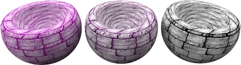
Color strength 0.2, 0.5, 1.0.
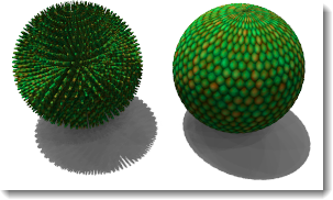
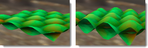
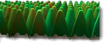
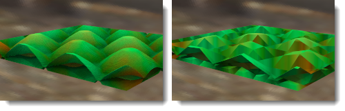
Simulates bumps and wrinkles on the surface of an object by perturbing the surface normals of the object. The underlying object is not changed. In the illustration, the material on the left uses displacement mapping, while the material on the right uses bump mapping set at its highest value. The edge and shadow are smooth for the bump-mapped material. See: Wikipedia article: Bump mapping.
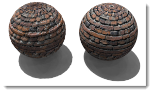
Bump strength, 0.5 (left) and 1.0 (right).
Fakes the lighting of bumps and dents without using more polygons to the render mesh. See: Wikipedia article: Normal mapping.
Normal maps work similar to bump maps, in that they modify the normal of the surface. The effect is essentially the same as bump; but normal maps allow more control over the normal than a bump. A bump map uses the grey average of the RGB in a bitmap. The RGB of a normal map corresponds to the modification of the XYZ of the normal.
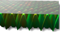
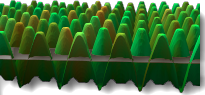
Causes an effect where the actual geometric position of the surface is displaced, often along the local surface normal. See: Wikipedia article: Displacement mapping.
Displaces the material using the color values to move points on the render mesh.
Note: Use displacement mapping sparingly for small objects. Displacement increases rendering time considerably.
The height of the highest point of displacement.
Sets the starting point of the displacement with reference to the surface normal.
Z-offset = -1.0
Z-offset = -0.5
Z-offset = 0.0
The size of the facets of the displacement mesh.
Select the color component of the material that will be affected by the bitmap.
Surface Component Altered by Map
Affects the shape of the highlight.
Affects the direction of the surface normals.
Offsets the material from the x- and y-axis.