Linetypes
| Toolbar | Menu |
|---|---|
|
|
File Settings |
The Linetype properties manage the linetype patterns for the current model.
- Using linetypes displays curves using dashed or dotted.
- Linetypes are assigned as object and layer properties.
- Linetypes affect only curve objects - not surfaces, solids, or other object types.
 New
New
Adds a linetype definition.
 Copy
Copy
Makes a copy of the selected linetype definition.
 Delete
Deletes the selected linetype definition.
 Import
Imports linetype definitions from a .3dm, .lin or .txt file.
In the Import Linetypes dialog box, select the linetypes to import.
 Add Defaults
Restores the default linetypes that have been deleted.
Model space scale
Sets the global scale factor for all linetype patterns in model viewports.
The SetLinetypeScale command can change this setting from Command-line.
 Search
Enter text to only list the linetypes with the text in their names.
Name and pattern
Continuous

Border

Center

DashDot

Dashed

Dots

Hidden

Pattern
Linetypes are defined by a comma-separated list of dash and gap lengths, always starting with a dash. A zero-length dash is a dot.
 Inches
Sets the display scale for linetypes to inches.
 Millimeters
Sets the display scale for linetypes to millimeters.
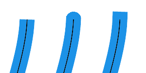
Cap style
Draws curve ends with the Flat (left), Round (middle), or Square (right) style.

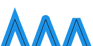
Join style
Draws curve joined corners with the Miter (left), Round (middle), or Bevel (right) style.

-
Enable Print display to see the cap and join styles in viewports.
Width Units (Pixels / Length Units)
Sets the width of the linetype to base on screen pixels or length units.
-
Pixel width is intended for screen capture only. It does not affect Print Preview in viewports or Print. To print linetypes with widths, set linetypes to use length unit width, or set the Print Width in object properties or layers.
-
Print width overrides linetype width in pixels, but not in length units.
-
Length unit width can display in viewports when print preview is on or off. Print width needs print preview to be on to display.
Taper
Enables line stroke for the linetype.
Taper Position (0 to 1)
Defines the location on a curve where the Taper Width applies.
0 is at the start of a curve and 1 is at the end.
The default value, 0.5, is halfway of the curve length.
- Use the Dir command to swap the start and end of a curve.
Taper Width
Controls the line width at the Taper Position.
End Width
Controls the line width at the end of the curve.
- The Width setting controls the start width.
Print and Display
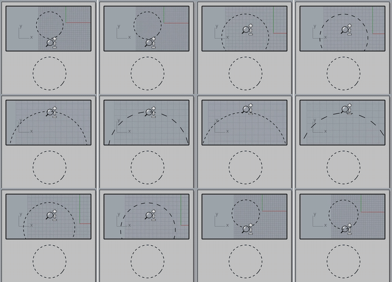
Use model units
When enabled (right), linetype segments in Detail views use model units to print.
When disabled (left), linetype segments in Detail views use Layout units to print. The linetype segments in Detail views and on the layout will be printed with the same scale regardless of the detail view scaling.

To set linetypes on objects
- In Object Properties, under Linetypes, click an option.
The default object linetype is By Layer.
To set linetypes on layers
- In the Layers panel, in the Linetypes column, select an option.
Or - Use the SetLayerLinetype command.
To define linetypes
- Use the controls to add a new type.
To create a new linetype
- Click the button.
A new linetype is added to the list. -
Click the name to rename it.
- While the new linetype is active, in the Pattern edit box specify the pattern for the linetype.
Example
"1,1" specifies a pattern with a 1-unit dash, followed by a 1-unit space.
"2,.5" specifies a pattern with a 2-unit dash, followed by a 0.5-unit space.
"1,.25,.25,.25" specifies a pattern with a 1-unit dash, .25-unit space, .25-unit dash, .25-unit space.
Complex dash-space patterns can be created this way.
To rename a linetype
- Select a linetype to highlight it.
- Click its name to type the new name.
- The default Continuous linetype cannot be renamed.
Linetype units
In Rhino linetype files, specify units with a designator. All subsequent line patterns will use the specified units. You can change back and forth within a single file. If neither designator is found, mm is used.
Example
#mm
Sets subsequent line patterns to mm units.
#inch
Sets subsequent line patterns to inch units.
To use linetypes defined in another Rhino model
- In Linetypes Document Properties, click the button to load linetype patterns from a Rhino file or an .lin file.
- Define linetypes in the template files.
- Copy a line with the linetype definition and paste it into your current model.
Related commands
|
Toolbar |
Menu |
|---|---|
|
|
Curve Curve from Objects > Extract Linetype Segments |
The ExtractLineTypeSegments command converts linetype patterns of the selected curves to curve segments and points.

-
The linetype properties of the extracted curve segments will be set to by object and continuous.
Command-line options
DeleteInput
Deletes the input curves.
GroupOutput
Makes the extracted curve segments of each input curve into a group.
OutputLayer=CurrentLayer/InputLayer
Places the extracted curve segments on the current layer or the same layer of the input curves.
| Toolbar | Menu |
|---|---|
|
|
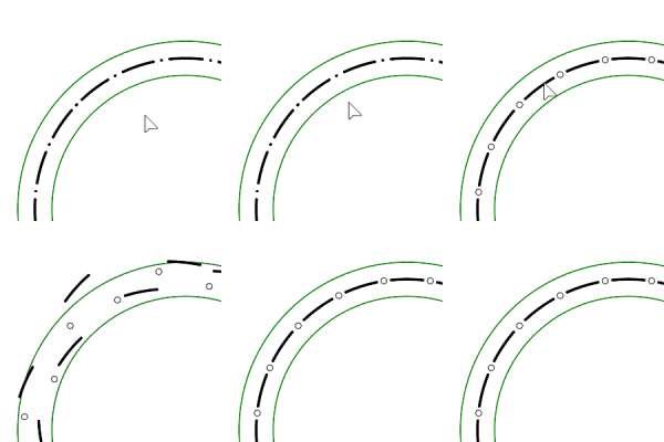
The LinetypeDisplay command configures how linetypes display in viewports.
Command-line options
DisplayLinetypes 
Turn on or off linetype display in viewports.
PatternBySegment
Restarts the linetype pattern at the beginning of each polyline segment.
PatternSegmentBreakAngle
Restarts the linetype pattern when the angle between polyline segments exceeds this value.
|
Toolbar |
Menu |
|---|---|
|
|
Window Panels > Linetypes |
The Linetypes command shows document linetype definitions in a tabbed panel.
![]() Linetypes panel
Linetypes panel
 New
New
Adds a linetype definition.
 Copy
Copy
Makes a copy of the selected linetype definition.
 Delete
Deletes the selected linetype definition.
 Import
Imports linetype definitions from a .3dm, .lin or .txt file.
In the Import Linetypes dialog box, select the linetypes to import.
 Add Defaults
Restores the default linetypes that have been deleted.
Model space scale
Sets the global scale factor for all linetype patterns in model viewports.
The SetLinetypeScale command can change this setting from Command-line.
 Search
Enter text to only list the linetypes with the text in their names.
Name and pattern
Continuous

Border

Center

DashDot

Dashed

Dots

Hidden

To sort linetypes
(For the Linetypes panel only)
-
Click the name or pattern header to sort the linetype list.

-
Right-click on a linetype to show the context menu.
 Assign to selected objects
Applies the linetype to the objects in selection.
-
Or select the curves and Shift+Double-click on the linetype pattern.
 Assign to layer
Applies the linetype to the selected layer.
 Select objects
Selects the objects displaying the linetype that can be By Layer or By Object.
-
Or double-click on the linetype pattern.
-
Only the object types supporting linetype display will be selected.
-
Objects in block instances using the linetype cannot be selected.
 Copy
Copy
Makes a copy of the linetype.
 Delete
Removes the linetype from the document.
 Add defaults
Restores the default linetypes that have been deleted.
Pattern
Linetypes are defined by a comma-separated list of dash and gap lengths, always starting with a dash. A zero-length dash is a dot.
 Inches
Sets the display scale for linetypes to inches.
 Millimeters
Sets the display scale for linetypes to millimeters.
Cap style
Draws curve ends with the Flat (left), Round (middle), or Square (right) style.

Join style
Draws curve joined corners with the Miter (left), Round (middle), or Bevel (right) style.

-
Enable Print display to see the cap and join styles in viewports.
Width Units (Pixels / Length Units)
Sets the width of the linetype to base on screen pixels or length units.
-
Pixel width is intended for screen capture only. It does not affect Print Preview in viewports or Print. To print linetypes with widths, set linetypes to use length unit width, or set the Print Width in object properties or layers.
-
Print width overrides linetype width in pixels, but not in length units.
-
Length unit width can display in viewports when print preview is on or off. Print width needs print preview to be on to display.
Taper
Enables line stroke for the linetype.
Taper Position (0 to 1)
Defines the location on a curve where the Taper Width applies.
0 is at the start of a curve and 1 is at the end.
The default value, 0.5, is halfway of the curve length.
- Use the Dir command to swap the start and end of a curve.
Taper Width
Controls the line width at the Taper Position.
End Width
Controls the line width at the end of the curve.
- The Width setting controls the start width.
|
Toolbar |
Menu |
|---|---|
|
|
The SetCustomLinetype command lets you edit an object's custom linetype properties in a floating dialog.
| Toolbar | Menu |
|---|---|
|
|
|
The SetLinetype command specifies a linetype for the selected curves.
Steps
- Select curves.
- In the Select Linetypes dialog box, select a linetype from the list.
| Toolbar | Menu |
|---|---|
|
|
|
The SetLayerLinetype command specifies a linetype for the specified layer.
Steps
- Specify a layer name.
- Specify a linetype.
| Toolbar | Menu |
|---|---|
|
|
|
The SetLinetypeScale command specifies the global linetype scale from the command line.
