OffsetSrf
| Toolbar | Menu |
|---|---|
|
|
Solid Offset Surface Offset Surface |
The OffsetSrf command copies a surface or polysurface so that locations on the copied surface are the same specified distance from the original surface.
Steps
- Select a surface or polysurface.
- Type the offset distance, and press Enter.
Infinite Plane: Type IP for InfinitePlane options.
Command-line options
Distance
Sets the offset distance.
Corner
Specifies how offset corner continuity handled. These options only apply if the offset direction is to the "outside" as shown in the image.
Sharp
Curves offset to the outside of a corner will be extended to meet at sharp corners with position (G0) continuity.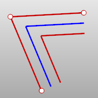
Round
Curves offset to the outside of a corner will be filled with arc segments with tangent (G1) continuity.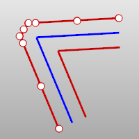
ThroughPoint
Offsets through a picked point instead of at a distance.
FlipAll
Flips the offset direction of all selected surfaces. Arrows indicate the positive offset direction.
Solid
Makes a closed solid from the input and offset surfaces by lofting a ruled surface between all of the matching edges.
Loose (Surfaces only)
The control point structure of the offset surface is identical to the original surface.
- This option is not available when any of the selected objects is a polysurface.
Tolerance
Sets the tolerance for the offset surface. Type 0 to use the default tolerance.
BothSides
Draws the offset on both sides of the original.
DeleteInput
Deletes (Yes) or keeps (No) the input objects.
Notes
- Positive values offset in the direction of the arrows. Negative values offset the other way.
- When a plane, torus, sphere, open cylinder, or open cone surface is offset, the resulting surface is exact. Free-form surfaces are offset to within the value of the Tolerance option.
- When offsetting a polysurface with free-form sub-surfaces, the results might have some surfaces missing.
- The output object adopts the rendering material from the input object.
See Also
OffsetMesh
Copies a mesh by moving the vertices a specified distance with different direction modes.
OffsetSubD
Makes a copy of a SubD by moving its vertices towards the normal direction with the specified distance.
| Toolbar | Menu |
|---|---|
|
|
Solid Shell |
The Shell command creates a hollowed out shell from a solid.
Shell only operates on simple, solid, manifold polysurfaces. These surfaces are removed and the remainder is offset inward, using the outer parts of the removed surfaces to join the inner and outer parts.
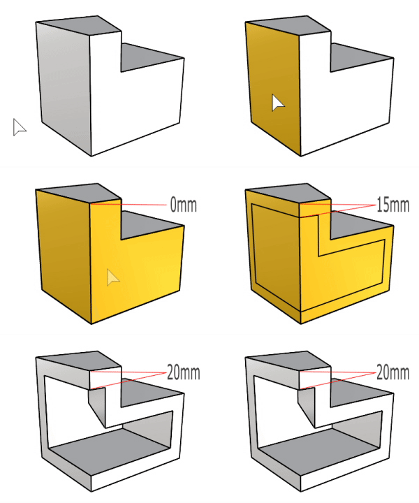
Two side surfaces of the object are selected for removal. The shelling thickness is 20 units.
Steps
Command-line options
Thickness
Specify the thickness for the shell.
DeleteInput
Specify if the input object will be deleted.
![]() DeleteInput=No supports History.
DeleteInput=No supports History.
EditThickness
Select a shelled object with History recorded to change the thickness.
Troubleshoot shelling
Shell and OffsetSrf for polysurfaces are works in progress. There are several known problem areas:
- Singular surfaces can cause problems, especially when the offset of the surface must be extended at the singularity. The extensions are done in OffsetSrf (Corner=Sharp) and shelling, which always uses sharp corners. These extensions happen when the offsets of adjacent surfaces come apart. Also, cone-like singularities cause problems in all cases.
- Complex vertices (ones with more than three edges) can be problematic, especially in shelling and sharp corner offsets and where some, but not all, of the surfaces at the vertex offset apart.
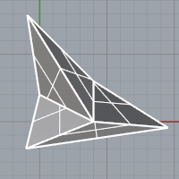
- OffsetSrf on polysurfaces with naked edges, where the naked edges make concave boundaries will not work correctly.
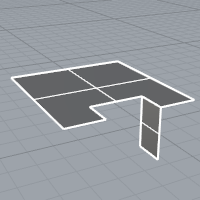
- If faces adjacent to the removed faces offset in such a way that the removed face must be extended to fill in the gap, it will fail.
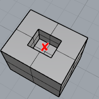
- Any surface whose offset self-intersects will cause a problem.