
This tutorial demonstrates how to get started modeling an object using photographs as reference material.

You will learn how to:
Trace images to create profile curves.
Sweep a cross-section along two rails to create the body segments.
Create the tail from a curve network.
Use blend surfaces to create the chest.
Edit control points to change the shape of a surface for the head.
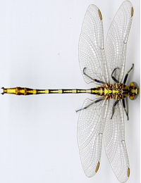
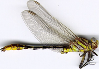
Note: The top and side views are actually of different specimens of this dragonfly. In the side view, the wings are folded up. We will be using the side view image only to draw the side view curves of the body.
On the Rhino Help menu, click Learn Rhino, and then click Tutorials and Samples.
In the Tutorials panel, under User's Guide, double-click the tutorial image files Dragonfly Top.jpg and Dragonfly Side.jpg.
On the File menu, click New to begin a new model.
In the Open Template File dialog box, select Small Objects - Millimeters.3dm, and click Open.
Drag the image file DragonFly Top.jpg from File Explorer and drop it onto a Rhino viewport.
In the Image Options dialog, select Picture, and click OK.
Move the cursor to the Top viewport, type 0, and press Enter.
This places the first corner at the construction plane origin, 0,0,0.
Type 50, and press Enter.
This sets the length of the Picture plane to 50 mm.
Move the cursor above the X axis, and click.
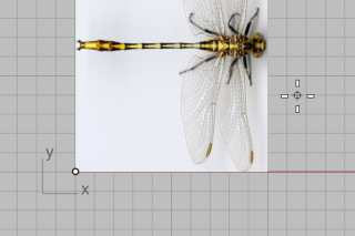
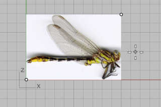
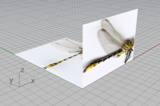
On the Object Snap toolbar, check Mid and End.
In the Perspective viewport, move the cursor near the tail of the top view image and hold the left mouse button.
The Mid tooltip appears to indicate the middle point of the edge is snapped.
Note: Do not release the left mouse button.

Drag the Picture plane, snap to the lower-left corner of the other Picture plane, and release the left mouse button.
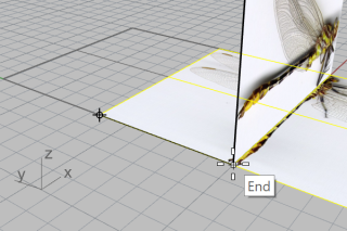
On the Status bar, turn on Gumball.

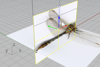
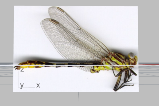
For more information about using Rhino's gumball feature, review the Help topic for the Gumball command.
Two video tutorials also help with learning to use the gumball
Hello Gumball! (https://vimeo.com/84954262)
Gumball Advanced (https://vimeo.com/260472052)
The Picture command creates a Picture material with the selected image as the texture and assigns the material to the Picture plane. Reducing visibility of the Picture material makes tracing the image easier.

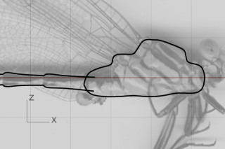
Black curves on the full color texture (left) and on a transparent grayscale texture (right).
In the Materials panel, two materials have been added by the Picture command.
Select both materials in the Materials panel.
Tip: Select a material, hold Shift, and select the other.
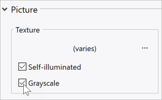
In the Texture settings below, check Grayscale.
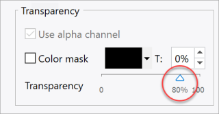
In the Transparency settings, drag the slider to 80%.
You can also double-click the triangle slider, and enter 80.
Select the two Picture planes and run the Lock command.
(Edit > Visibility > Lock)
This makes it so the Picture planes cannot be selected. Selecting curves on or behind the Picture planes will be easier.
Start the Curve command.
(Curve > Free-Form > Control Points)
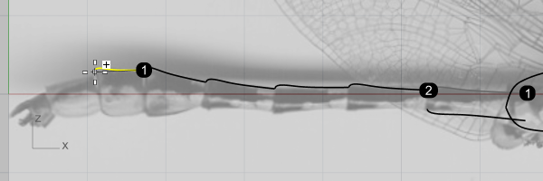
In the Front viewport, start the curve at the neck (1).
Trace along the upper profile of the chest and end the curve at (2) where the chest and body connect.
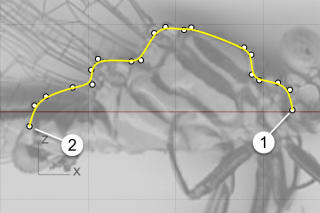
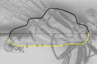
Draw another curve along the lower profile of the chest.
Use the End object snap to start and end the curve at the endpoints of the first curve.
The body consists of several segments. We only need to draw the profiles of one segment.
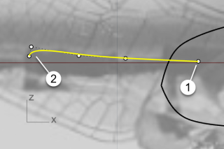
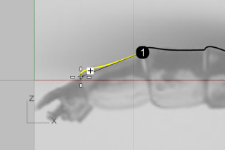
Start a curve at (1) in the chest and above the ends of the chest profiles.
Reference the image and end the curve at the end of the first segment.
Tip: Use five points to draw the curve. Place the last two points close to form a curly end (2).
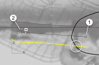
Select the curve, and start the Mirror command.
(Transform > Mirror)
Pick at (1) and then (2) to define the mirror plane.
Tip: The mirrored curve has to intersect with the lower chest profile.
Select the upper body segment profile, and start the Orient command.
(Transform > Orient > 2 Points)
Set command-line options to Copy=Yes and Scale=1D.
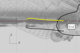
Snap to the right end of the curve, and click to place the first reference point.
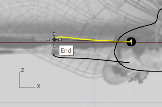
Snap to the left end of the curve, and click to place the second reference point.
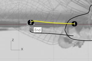
Snap to the same end again, and click to place the first target point.
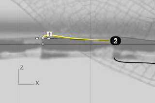
Using the image as a reference, click at the end of the second body segment.
Snap to the current end, click, and continue duplicating more curves along the upper body profile.
Click at the end of the last body segment, and press the ESC key to end the command.
Use the same procedure to duplicate the other curve along the lower body profile.
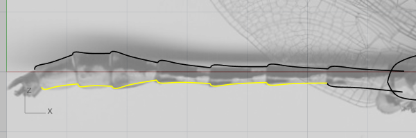
The last three lower body segment profile curves do not match the image. We will use control point editing to improve them.
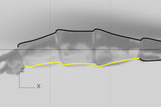
Select one of the curves.
Its control points turn on automatically.
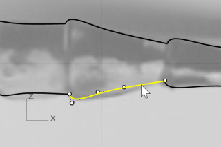
Move the control points to make the curve match the image.
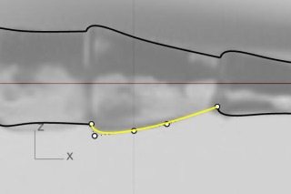
Adjust the other two curves.
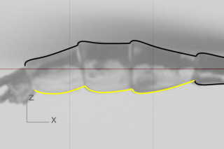
Select all body segment profile curves, and Join them into two polycurves.
(Edit > Join)
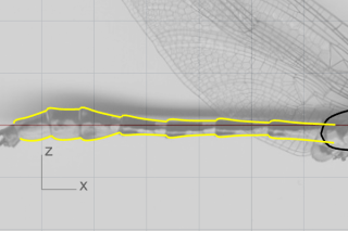
At the command-line, click the Vertical option.
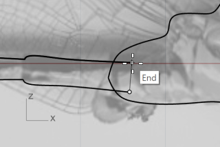
In the Front viewport, snap to the two ends of the body profile curves to create a circle.
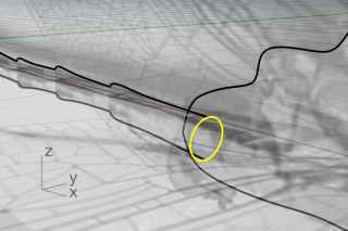
Start the Sweep2 command.
(Surface > Sweep 2 Rails)
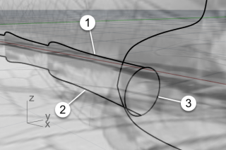
In the Perspective viewport, select the two body profile curves (1) and (2), and the cross-section circle (3) in order. Press Enter when done.
Press Enter one more time to accept the default seam location.
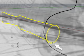
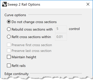
In Sweep 2 Rail Options, set the options as shown below, and click OK to create the surface.
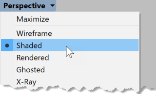
On the Perspective viewport title menu, click Shaded to see the surface.
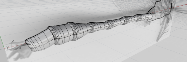
Start the Curve command.
(Curve > Free-Form > Control Points)
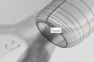
Use the Quad object snap to start the curve from the top quadrant point of the body edge.
Continue drawing the curve in the Front viewport.
Use four points to create the curve.
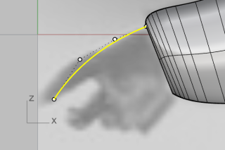
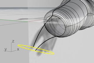
Create another curve from the bottom quadrant point of the body edge.
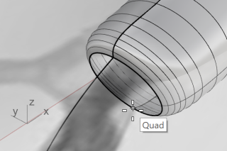
Continue drawing the curve in the Front viewport.
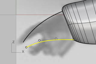
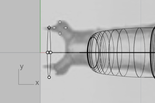
Create an Ellipse from its diameter.
(Curve > Ellipse > Diameter)
At the command-line click the Vertical option.
To draw the ellipse vertical to the Front construction plane, in the Front viewport, use the End object snap to place the first and second points of the ellipse at the ends of the two curves.
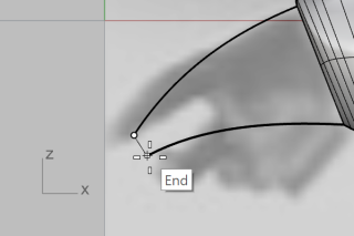
In the Top viewport, reference the image, and place the third point of the ellipse.
Start the InterpCrv command.
(Curve > Free-Form > Interpolate Points)
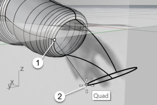
In the Perspective viewport, use the Quad object snap to start the curve from the left quadrant point of the body edge (1).
End the curve at the left quadrant point of the ellipse (2).
In the Front viewport, select the curve, and move the two control points up a small distance.
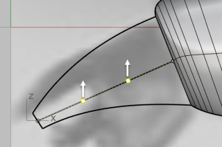
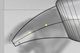
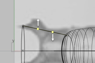
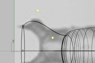
In the Top viewport, move the two control points in the vertical direction to make an "S" shape.
Tip: To maintain the curve's shape in the Front viewport, move the control points in the Top viewport only in the y‑direction.
Mirror (Transform > Mirror) the curve to the other side.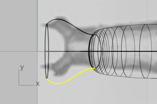
Now we have a curve network that we can use to create the tail surface.
Start the NetworkSrf command.
(Surface > Curve Network)
In the Perspective viewport, select the four curves, the ellipse, and the body edge, and press Enter.
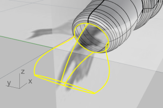
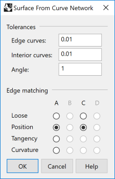
In the options dialog, set the options as shown below, and click OK.
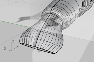
Use the SelCrv command to select all the curves in the model.
(Edit > Select Objects > Curves)
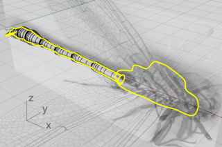
Hold the Ctrl key and click on the two chest profile curves to deselect them.
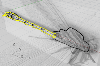
Hide all the curves that will not be used in the future.
(Edit > Visibility > Hide)
Start the Join command.
(Edit > Join)
Select the body and tail surfaces, and press Enter.
The body and tail are joined into a single object.
While the new body-tail object is still selected, run the Cap command.
(Solid > Cap Planar Holes)
A planar surface is added to each open end to make it a closed object.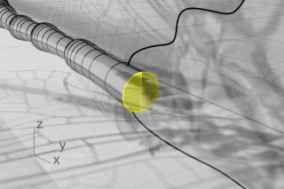
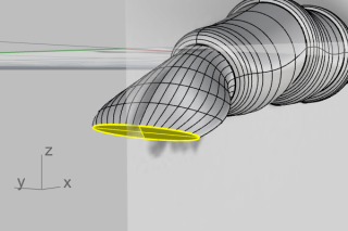
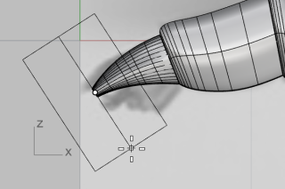
We will create a cylinder and use it to trim the tail.
Start the Cylinder command.
(Solid > Cylinder)
Set the command-line option Solid=Yes, and click 2Point.
Use the Quad object snap to place the start (1) and end (2) of the cylinder base at the left and right quadrant points of the tail edge.
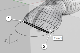
Set the command-line options DirectionConstraint=None and BothSides=Yes.
In the Front viewport, move the cursor to make the preview cylinder roughly perpendicular to the tail and click.
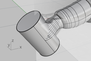
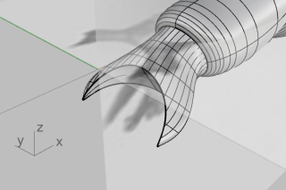
Start the BooleanDifference command.
(Solid > Difference)
Select the body-tail object as the object to subtract from, and press Enter.
Select the cylinder as the object to subtract with, and press Enter.
We will make two dummy surfaces to help create one side of the chest.
Turn on Gumball.
Select the two chest profile curves in the Perspective viewport.
Drag the small dot on the green arrow of the Gumball widget for a short distance.
The two curves are extruded into two surfaces. They are the dummy surfaces.
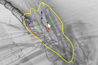
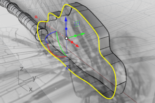
While the curves are still selected, run the Hide command.
(Edit > Visibility > Hide)
Start the BlendSrf command.
(Surface > Blend Surface)
Select the two edges of the dummy surfaces.
Tip: Select the two edges close to the same end.
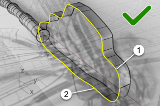
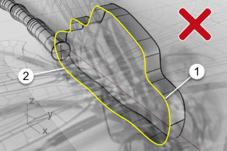
In the options dialog, click the lock icon to link the two sliders.

Set the options as shown in the illustration below.
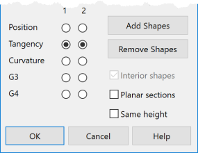
Look at the Top viewport and drag the sliders to the left until the blend surface profile matches the chest profile in the top image.

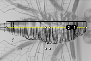
Click OK to create one side of the chest.
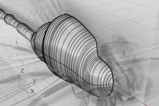
Delete the two dummy surfaces.
Select the chest surface, and start the Mirror command.
(Transform > Mirror)
With the Perspective or Top viewport active, click the command-line option XAxis.
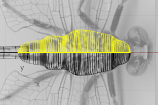
Join both sides into a whole chest.
(Edit > Join)
The head is deformed by control points editing from an ellipsoid.
Start the Sphere command.
(Solid > Sphere > Center, Radius)
In the Front viewport, pick at (1) for the sphere center and (2) for the radius.
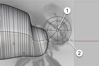
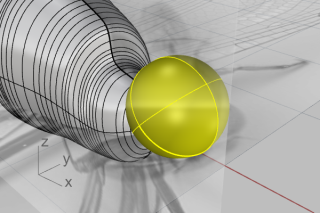
In the Top viewport, select the sphere, and turn on Gumball.
Drag the Y scale handle (the small green rectangle) down for a short distance.
The sphere became an ellipsoid.
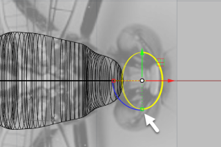
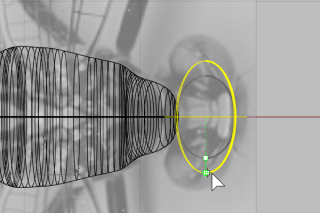
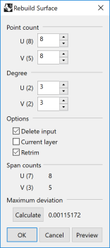
Rebuild the ellipsoid.
(Edit > Rebuild)
In the Rebuild Surface options dialog, set the options as shown in the illustration below, and click OK.
Select the head, and press F10 to turn on its control points.
Start the SelCircular command.
(Edit > Select Objects > Area and Volume Select > Circular)
In the Front viewport, as shown below, click at (1) to set the center of the selection circle.
Click at (2) between the outermost two rows of control points to define the size of the selection circle.
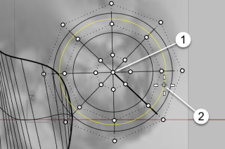
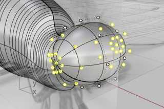
In the Top viewport, drag Gumball's X move control (the red arrow) to the left.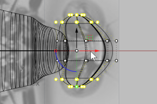
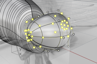
In the Front viewport, window-select the control points as illustrated.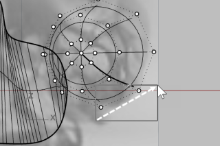
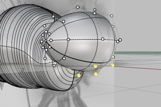
Drag Gumball's XY plane control toward the lower-right.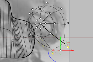
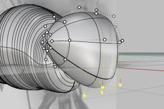
Press ESC to turn off control points.
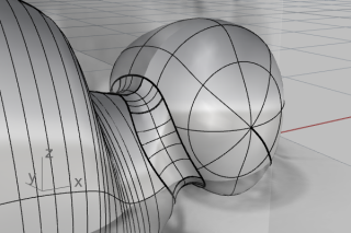
The neck is a blend surface between the head and body. You will first combine the head and body, and then create a blend surface along the edges between them.
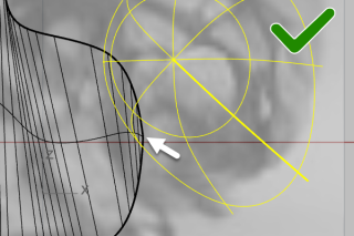
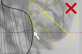
In the Front viewport, move the head to enclose the endpoint of the chest as needed.
If the endpoint of the chest is not inside the head, the neck surface will fail to create.
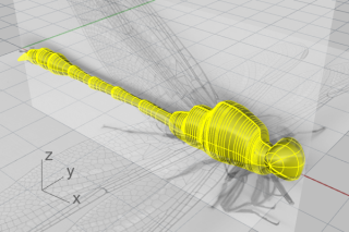
Select the head, chest, and body, and run the BooleanUnion command.
(Solid > Union)
Start the BlendEdge command.
(Solid > Fillet Edge > Blend Edge)
Set the command-line options NextRadius=0.5 and Preview=Yes.
Select the edges between the head and chest, and press Enter.
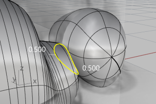
Preview the result, and press Enter to create the neck.
The eyes are simple ellipsoids.
Start the Sphere command.
(Solid > Sphere > Center, Radius)
In the Perspective viewport, pick two points around the head to create a sphere.
The sphere size does not matter.
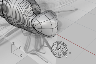
Tune on Gumball and drag the Z scale handle (the small blue rectangle) up to squeeze the sphere into an ellipsoid.
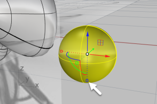
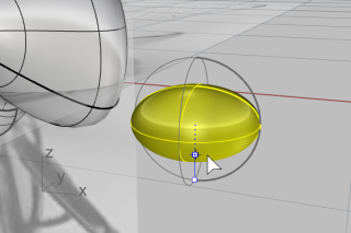
Turn off Gumball.
Select the eye ellipsoid and start the OrientOnSrf command.
(Transform > Orient > On Surface)
In the Perspective viewport, snap to the center of the ellipsoid, and click.
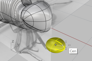
Pick another point on the construction plane as the reference point.
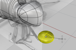
Select the head as the target surface.
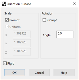
In the options dialog, set the options as shown in the illustration below, and click OK.
Move the ellipsoid on the surface to a proper location, and click.
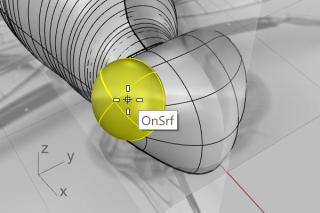
Disable all object snaps.
Move the cursor to define the size of the eye, and click.
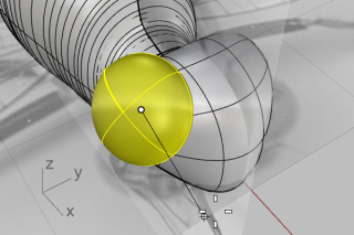
Select the eye and start the Mirror command.
(Transform > Mirror)
On the Status bar click Record History .
At the command-line, click the XAxis option.
Use Gumball to adjust the position, size, and orientation of the first eye.
History will update the mirrored eye on the other side.
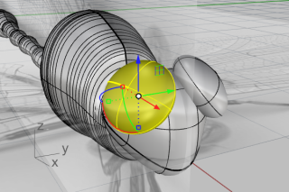
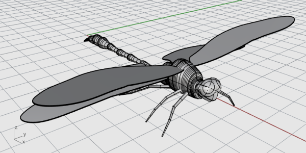
The wings are solids created from closed planar curves.
Hide the body.
(Edit > Visibility > Hide)
Double-click the Top viewport title to maximize the viewport.
Use the Curve command to trace a wing on one side.
(Curve > Free-Form > Control Points)
Tip: Place the last control point at the first control point to make a closed curve.
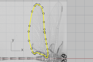
Draw the other wing on the same side.
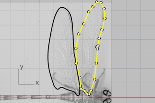
Set the command-line options BothSides=No and Solid=Yes.
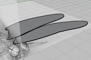
Use Gumball to move the wings up.
Place the front wing higher than the back wing.
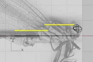
In the Top viewport, Mirror the wings to the other side.
(Transform > Mirror)
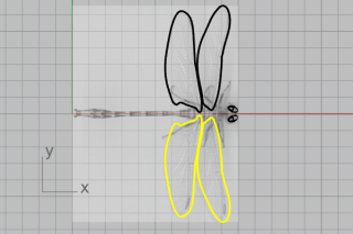
Hide the solid wings and the outline curves.
(Edit > Visibility > Hide)
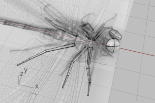
The legs are pipes created from polylines with various radii.
Start the Polyline command.
(Curve > Polyline > Polyline)
In the Top viewport, start every polyline close to the center line of the body.
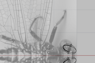
Trace down the center line of each leg with four points (three segments).
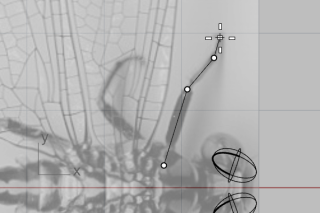
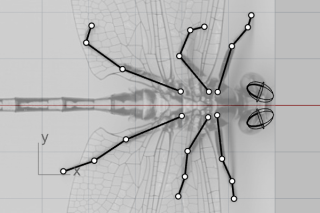
In the Perspective viewport, select a polyline, and use Gumball to move the control points down.
Tip: Look at the Front viewport to help locate the points.
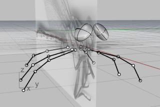
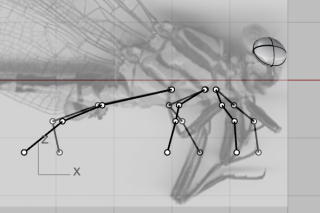
You will have to use your imagination a little for this since the two pictures do not show the legs of the same dragonfly.
Start the Pipe command and select a polyline.
(Solid > Pipe)
Type 0.4, and press Enter for the start radius.
Type 0.1, and press Enter for the end radius.
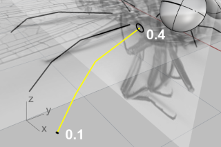
Use the End object snap to snap to the corner between the first and second segments and click.
Type 0.3, and press Enter.
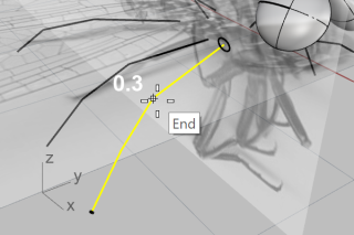
Snap to the corner between the second and third segments and click.
Type 0.2, and press Enter.
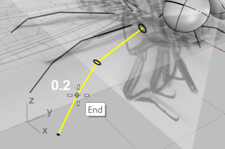
Press Enter again to create the pipe.
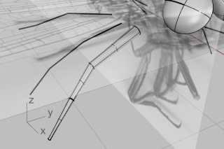
Create the other five legs with the same procedure.
Start the ShowSelected command.
(Edit > Visibility > Show Selected)
Select the body and wings, and press Enter.
Unlock the Picture planes and hide them.
(Edit > Visibility > Unlock)
Use Gumball to rotate the wings slightly to add realism.
Rhino for Windows © 2010-2018 Robert McNeel & Associates. 24-Nov-2021