Digitize
The Digitize command connects and initializes a 3-D digitizing arm.
使用 3D 量测手臂入门
- 选择量测手臂的型号。
- 使用量测手臂在真实世界中取一点为原点。
- Use the arm to pick an x axis in the real world.
- Use the arm to pick a y axis with digitizer in the real world.
You do not need to ensure that the y axis is perpendicular to the x axis, Rhino will do it for you.
- 在 Rhino 里取一点为原点。
- 按 使用世界座标系统。
- Pick the x axis in Rhino.
- Pick the y axis in Rhino.
其它可与量测手臂配合使用的指令
无论什么时候,只要 Rhino 提示您取一点的时候就可以使用量测手臂。因此,所有在曲线功能表里的指令都可以用量测手臂为输入来源。您可以使用量测手臂画直线、圆弧、圆、曲线...,就如同使用鼠标一样。
代替脚踏板
DigClick 指令可以模拟踩下脚踏板取点的动作,F12 键预设为此指令的快速键,如果您觉得按 F12 取点比使用脚踏板方便,您可以使用 F12 键代替脚踏板。
量测大型物件
量测大型物件时,您可以先量测物件的一部分,标示一些参考点,再量测下一部分,标示的参考点要同时位于两个部分的量测范围内。
设定参考点
- 在物件上标示参考点
- 以工作桌校正量测手臂。
- 量测第一、二组参考点。
- 移动量测手臂至第二、三组参考点之间,使量测手臂可以同时量测到第二、三组参考点。
- 以第二组参考点校正量测手臂。
- 量测第三组参考点。
- Continue moving from one set of reference points to the next until all the reference points are digitized.
在 MicroScribe 上使用非标准探针
如果您的 MicroScribe 使用的是非标准探针,必需依照下列的说明编辑 mstip.dat 档,mstip.dat 文件里也有此编辑说明。
设定 MicroScribe 使用非标准探针
Faro 量测手臂疑难排解
In the Faro Hardware Setup dialog box, changing the Trigger Mode from Internal (normal) to External causes Rhino to crash.
目前并无法修正这个错误。
相关指令
The DigBeep command turns digitizer pedal sound feedback on and off.
The DigCalibrate command calibrates a 3-D digitizer.
步骤
- 在实体模型上或附近取一点为原点,此点为量测手臂的座标系统原点。
- Pick an x axis on or near your physical model that is on the x axis of the digitizer coordinate system.
- Pick a y axis on or near your physical model that is on the y axis of the digitizer coordinate system.
Rhino will automatically make the y axis orthogonal to the x axis in the plane of the three points you pick, so the y axis point in the digitizer coordinate system need not be orthogonal to the x axis.
- 在 Rhino 里取一点为原点,量测手臂座标系统的原点会与此点对应。
- 如果您想让量测手臂的座标系统与 Rhino 里的世界座标系统对应,按 即可。
- Pick an x axis in Rhino that corresponds to the x axis of the digitizer coordinate system.
- Pick a y axis in Rhino that corresponds to the y axis of the digitizer coordinate system.
重新校正的方法
在量测过程中常常需要重新校正量测手臂,使 Rhino 的模型空间与真实世界保持同步。有时候因为量测手臂或被量测的物件受到碰撞而轻微位移,或是在某个运行阶段结束后需要关闭 Rhino,都需要重新校正量测手臂。不论是什么原因导致需要重新校正量测手臂,设定几个重新校正时需要用到的参考点会非常有用。
概观
- 将量测手臂与被量测的物件固定在工作桌上。
- 校正量测手臂,使被量测的物件可以正确地定位至 Rhino 的模型空间中。
- 在被量测的物件上标示三个参考点,这三个参考点可于需要重新校正量测手臂时使用。
- 量测这三个点,在 Rhino 的模型空间中放置三个对应点。
- 任何需要重新校正量测手臂时,都可以使用被量测物件上的三个参考点与 Rhino 模型空间中的三个对应点来校正量测手臂。
第一次校正
- 以量测手臂在工作桌上取一点为原点。
- Use the arm to pick an x axis on the table.
- Use the arm to pick a y axis on the table.
- 按 将工作桌上的原点及 XY 轴与 Rhino 模型空间中的世界座标系统对应。
建立参考点
- 使用油性笔在被量测的物件上标示出三个点。
- Label each point O, X, and Y for the origin, x, and y axes.
- 执行 Polyline 指令。
- Draw a polyline from X to O to Y. This is the reference polyline.
It may be useful to move this polyline to a layer called "reference points" for later use.
- Use the Dot command to label the endpoints and vertex of the polyline X, Y, and O.
量测手臂或被量测的物件被移动或是您需要重新启动 Rhino 时,可以使用这些参考点重新校正量测手臂,使新量测的资料可以与之前量测的资料对齐。
重新校正量测手臂
- Use the arm to pick origin point O on the real object.
- Use the arm to pick x axis point X on the real object.
- Use the arm to pick y axis point Y on the real object.
- In Rhino, snap to the vertex of the reference polyline labeled O to map origin.
- In Rhino, snap to the endpoint of the reference polyline labeled X to choose the x axis.
- In Rhino, snap to the endpoint of the reference polyline labeled Y to choose the y axis.
The DigCamera command sets the current viewport camera location and direction based on the digitizer probe position and direction - I, J, K coordinates.
| 指令行选项 |
|
公差
|
探针移动多少距离后才会开始带动视图变更。
|
The DigClick command lets you pick points from within Rhino instead of using the digitizer's foot pedal to pick points.
步骤
- Set up a function key (such as F12) with the DigClick command, so when you press the function key, it is as if you pressed the foot pedal.
The DigDisconnect command disconnects the 3-D digitizer.
The DigLine command digitizes a line that starts at the probe point and points away from the digitized surface.
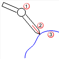
探针 (1)、直线 (2)、物件 (3)。
步骤
- 以量测手臂的探针在物件上一点为直线的起点。
建立一条以探针的尖端为起点,探针的方向为向量的逆向直线。
The DigPause command pauses the 3-D digitizer so that it does not interfere with using the mouse.
The DigScale command sets the scale factor for digitized points.
步骤
- 输入以量测手臂取点时的缩放比。
以公尺为量测单位,请输入 0.0254。
以公分为量测单位,请输入 2.54。
以毫米为量测单位,请输入 25.4。
The DigSection command creates planar cross sections using the 3-D digitizer.
步骤
- 画出基准平面。
请参考 Rectangle 指令的选项说明。
基准平面是一个所有断面都会与它平行的平面,放置数个量测平面可以快速地建立被量测物件的断面曲线。每当量测手臂的探针通过量测平面时,Rhino 就会取一个点。
量测平面是由一个基准点、方向及间距所定义,所有量测平面会与基准点与方向点所构成的方向垂直。
- 指定断面轴的起点。
第一个断面会通过断面轴的起点。
- 指定断面轴的终点与设定间距。
您可以设定断面与断面之间的间距,也可以设定有几个断面平均分布于断面轴的起点与终点之间。
- 以量测手臂探针接触被量测的物件,并踩住脚踏板。
踩住脚踏板时,只要量测手臂的探针通过一个断面,Rhino 就会取一个点。当您要让量测手臂探针离开物件时,可以暂时放开脚踏板,避免 Rhino 建立一些无用的取样点,要再开始取点时可以再次踩住脚踏板。
- 按 结束指令。
结束量测物件时,每个量测平面都会建立一条通过量测点的曲线。此时,量测点还处于选取状态下,您可以将这些点移动至其它图层或将它们删除。
| 指令行选项 |
|
工作平面位置
|
平均间隔
平面数 = <数值>
间隔距离
平面间距 = <数值>
|
|
点距
|
设定点之间的最小距离。
|
|
点
|
描绘时建立点。
|
|
曲线
|
描绘时建立曲线。
|
|
多重直线
|
描绘时建立多重直线。
|
The DigSketch command sketches a curve using a 3-D digitizer.
步骤
- Move the arm to the location where you want to start digitizing, push and hold the pedal, and drag the arm through the curve to digitize.
- To create a closed curve, type C when creating a curve.
| 指令行选项 |
|
Points
|
描绘时建立点。
|
|
曲线
|
描绘时建立曲线。
|
|
多重直线
|
描绘时建立多重直线。
|
|
点距
|
设定点之间的最小距离。
|
请参考
使用量测手臂
Rhinoceros 6 © 2010-2017 Robert McNeel & Associates. 25-6月-2018

