To use 2-D construction plane coordinates
At a prompt, type the coordinate in the format x,y where x is the x-coordinate and y is the y-coordinate of the point.
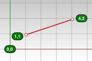
A line from 1,1 to 4,2.
Make the mouse cursor go where you want it to go.
Normally, dragging the mouse moves the cursor on the construction plane in the active viewport. Simply move the cursor to another viewport to change the construction plane.
You can also restrict the cursor movement in the following ways:
| ● | To a specified coordinate point |
| ● | Angle |
| ● | Distance |
| ● | Vertical |
| ● | To a coordinate point relative to the current location |
| ● | In a specified direction based on the cursor location |
| ● | To the x, y, or z-coordinate of specified location |
Places the cursor at a specified x-, y-, and z-location.
When Rhino prompts you for a point, if you type x and y Cartesian coordinates, the point will lie on the construction plane of the current viewport.
To use 2-D construction plane coordinates
At a prompt, type the coordinate in the format x,y where x is the x-coordinate and y is the y-coordinate of the point.
A line from 1,1 to 4,2.
To use 3-D construction plane coordinates
At a prompt, type the coordinate in the format x,y,z where x is the x-coordinate, y is the y-coordinate, and z is the z-coordinate of the point.
There are no spaces between the coordinate values.
To place a point 3 units in the x-direction, 4 units in the y-direction, and 10 units in the z-direction from the construction plane origin, type 3,4,10 at the prompt.
Rhino contains one world coordinate system. The world coordinate system cannot be changed. When Rhino prompts you for a point, you can type coordinates in the world coordinate system.
The arrow icon in the lower left corner of each viewport displays the direction of the world x-, y-, and z-axes. The arrows move to show the orientation of the world axes when you rotate a view.

To use 2-D world coordinates
At a prompt, type the coordinate in the format wx,y.
To use 3-D world coordinates
At a prompt, type the coordinate in the format wx,y,z
To place a point 3 units in the world x-direction, 4 units in the world y-direction, and 10 units in the world z-direction from the world origin, type w3,4,10 at the prompt.
Note
| ● | W0 is a shortcut for w0,0,0. |
| ● | There are no spaces between the coordinate values. |
Locks the next point will be placed at a specified angle relative to the last point.
To constrain to an angle
Type an angle at the command prompt in the format <angle and press Enter.
The cursor moves along a line at the specified angle.
The angle constraint can also be used for finalizing the pick in elevator mode.
Example
| 1. | Start the Line command and place the first line point. |
| 2. | At the End of line… prompt, type <20. The line is restricted to 20-degree angle increments. |
| 3. | Click to place the point, or, type a distance, and press Enter. |
Locks the next point will be placed at a specified distance from the last point.
To constrain to a distance
Type a number at the command prompt and press Enter.
The marker moves around the last point at the specified distance.
Example
| 1. | Start the Line command and place the first line point. |
| 2. | At the End of line prompt, type 4. The line endpoint moves around the last point 4dim units away. |
| 3. | Click to place the point, or, type an angle, and press Enter. |
Rhino remembers the last point used, so you can enter the next point relative to it. Relative coordinates are useful for entering a list of points where the relative locations instead of absolute locations of the points are known. Use relative coordinates to locate points according to their relationship to the previous active point.
To use relative coordinates
At a prompt, type the coordinates in the format rx,y where r signifies that the coordinate is relative to the previous point.
For example
| 1. | Start the Line command. |
| 2. | At the Start of line… prompt, click to place the first end of the line. |
| 3. | At the End of line… prompt, type r2,3, and press Enter or Space. The line is drawn to a point 2 units in the x-direction and 3 units in the y-direction from the last point.
|
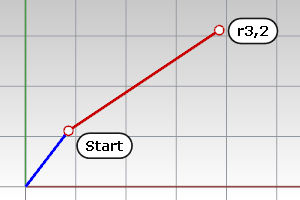
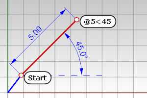
The distance and angle constraints can be combined.
To use both distance and angle
At a prompt type the @ symbol, or type r to set the distance relative to the last point.
Example
| 1. | Start the Line command and place the first line point. |
| 2. | At the End of line… prompt, type @5<45 or r5<45. The line is drawn 5 units from the last point at the angle 45 degrees from the first point.
|
The Tab key locks the cursor's direction of travel.
Example
| 1. | Start the Line command and place the first line point. Use an object snap to locate a specific location on another object. |
| 2. | Press Tab. The marker is now constrained along the line between the first point and the point where the marker, was when you pressed Tab. If grid snap is on and ortho is activated, the direction lock snaps to grid lines. |
Tips
| ● | Use direction lock constraint when you want the line to pass through the end of a curve and then go beyond it. Turn on end object snap. When you move the cursor close to the end of the curve, the marker snaps to the curve end. Press Tab and then move the mouse beyond the curve end and pick. The line will pass through the end of the curve. |
| ● | Use direction lock constraint combined with the distance constraint to draw a curve of a specified length and then constrain the angle with the Tab key. |
Specify a point that is a given distance above or below a point on the construction plane.
Draw a curve using elevator mode
| 1. | Start the Curve command and place the first point. |
| 2. | At the Next point of curve... prompt, pick another location in the perspective viewport. |
| 3. | At the Next point... prompt, hold |
| 4. | Drag the mouse in the perspective viewport. A tracking line displays, indicating that the marker is constrained to move perpendicular to the construction plane. Click the left mouse button to select the point. Notice the location of the marker in the other views. |
Drag objects perpendicular to the construction plane using elevator mode
| 1. | Select the objects to move. |
| 2. | Hold A tracking line will connect the point you picked to the marker, indicating the new location of the selection set. |
| 3. | Release the left mouse button to place the objects. |
Turn off elevator mode if you have started elevator mode in error
| 1. | After starting elevator mode, hold |
| 2. | Continue with picking locations. You can start elevator mode in another location. |
Example with angle and elevator mode
| 1. | Start the Line command and place the first line point. |
| 2. | At the End of line… prompt, move the mouse to the location where the line should end, activate elevator (press A line is drawn at 30 degree angle to the construction plane, ending on the elevator line. |
Multiple elevator
| 1. | Press |
| 2. | Change viewports, release A new elevator mode starts relative to the new construction plane. |
Canceling elevator
| 1. | Press |
| 2. | Release |
Elevator mode can also be activated from direction lock, but only if the point can be truly 3‑D.
Note
| ● | Type a number at the command prompt to specify the elevation of the point. Positive numbers are above the construction plane, negative numbers are below. |
| ● | Specifying 3-D points using 2-D input devices (the mouse and monitor) is aided with construction planes. Anything drawn in Rhino by simply picking points is always drawn on the construction plane of the current viewport. |
Point filters extract individual x-, y-, and z-coordinate values from different points to create a new, composite point.
You can use point filters to pick one coordinate value at a time while temporarily ignoring other coordinate values. If you use point filters with object snaps, they extract coordinate values from an existing object so you can locate another point.
After you specify the first value, you are prompted for the remaining values.
Point filters only work when 3-D input is allowed, and you cannot start with one point filter and then apply another one.
Example
To place a point at the x-coordinate of the right end of a line and the y-coordinate of the left end of a line.
| 1. | Start the Point command. |
| 2. | At the Location of point object prompt, type .x. |
| 3. | At the X coordinate of prompt, with the End object snap activated, pick the right end point of the line. |
| 4. | This sets the x-coordinate of the point to the right end of the curve. |
| 5. | At the next Location of point object prompt, type .y. |
| 6. | At the Y coordinate of prompt with the End object snap activated, pick the left endpoint of the line. This sets the y-coordinate of the point to the left end of the curve. |
| 7. | At the Location of point object prompt, pick to place the point. If you specified an x-value, the coordinate of the new point matches the x-value of the first point and the y,z-value of the second point. |
The following filters are possible:
.x
.y
.z
.xy (.yx)
.xz (.zx)
.yz (.zy)
.wx
.wy
.wz
.wxy (.wyx)
.wxz (.wzx)
.wyz (.wzy)
See also
Turn on a system of temporary reference lines and points.
Constrain the marker to an exact location on an object such as the center of a circle or the midpoint of a line.
Restrict cursor movement to an angle.
Rhinoceros 5 © 2010-2015 Robert McNeel & Associates. 17-Sep-2015