The CageEdit command deforms objects smoothly using two-, and three-dimensional cage objects.
Note
| ● | Cage editing allows smooth deformation of surfaces with dense control points. |
| ● | Polysurfaces are not broken apart at the seams by CageEdit deformation. |
| ● | CageEdit allows both overall deformation and partial deformation of an object. |
| ● | The control object can be made with the Cage command or can be an existing surface or curve. |
| ● | To use the captive object as its own control, select an edge of same object or a face of a polysurface. |
| ● | History is built in regardless of the History setting. |
Steps
| 1. | Select the captive objects (objects to edit). |
| 2. | Select or create a control object, which defines the region to edit. |
Options for cage control object
The BoundingBox option uses the object bounding box to determine the box location.
BoundingBox options
CoordinateSystem
The coordinate system for the bounding box.
CPlane
Construction plane coordinates.
World
3Point
Pick three points to establish a coordinate system.
Note: See the BoundingBox command for detailed option descriptions.
Cage Points
The Cage Points option specifies the number of control points and degree of the cage in each direction as appropriate for the cage object.
PointCount (UV or XYZ)
Specifies the number of control points in each direction of the line, rectangle, or box.
Degree (UV or XYZ)
Specifies the degree in each direction of the line, rectangle, or box.
Line
Draw a line to be used as the control object.
Line Cage Points
Degree
The Degree of the line.
PointCount
The number of control points.
Rectangle
Draw a rectangle to be used as a control object.
Rectangle options
3Point
The 3Point option draws the rectangle using two adjacent corner locations and a location on the opposite side.
Vertical
The Vertical option draws the rectangle perpendicular to the construction plane.
Center
The Center option draws the rectangle around a center point.
Note: See the Rectangle command for detailed option descriptions.
Cage Points
UDegree / VDegree
Sets the Degree of the surface in the u- and v-directions.
UPointCount / VPointCount
The number of control points in the u- and v-directions.
Box
Draw a box to be used as a control object.
Box options
Default
The default option draws the base rectangle using two opposite corners.
BoundingBox
The BoundingBox option uses the object bounding box to determine the box location.
Note: See the BoundingBox command for detailed option descriptions.
Diagonal
The Diagonal option draws the base rectangle from two diagonal corners. No option for side length is offered.
3Point
The 3Point option draws the base rectangle using two adjacent corner locations and a location on the opposite side.
Vertical
The Vertical option draws the base rectangle perpendicular to the construction plane.
Center
The Center option draws the base rectangle around a center point.
Note: See the Box command for detailed option descriptions.
Cage Points
The Cage Points option specifies the number of control points and degree of the cage in each direction as appropriate for the cage object.
PointCount (UV or XYZ)
Specifies the number of control points in each direction of the line, rectangle, or box.
Degree (UV or XYZ)
Specifies the degree in each direction of the line, rectangle, or box.
Deformation
Accurate
The Accurate option makes the deformation slower to update and may result in denser surfaces when deformed objects are refit.
Fast
The Fast option creates surfaces that have fewer control points and are therefore less accurate.
PreserveStructure=Yes/No
The PreserveStructure option specifies whether the control-point structure of a curve or surface will be maintained after the deformation.
The Yes option preserves the control point structure of the surface. Deformation may be less accurate if there are too few control points in on the object.
The No option refits the objects as needed with more control points to allow accurate deformation.
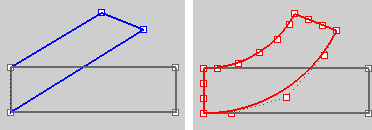
PreserveStructure=Yes (left); PreserveStructure=No (right).
Note: This option does not apply to polysurfaces, and will not be displayed if polysurfaces are selected for editing.
Region to edit
Global
The Global option deforms objects throughout 3-D space. The influence of the control object on the captives is not limited to the region inside cage objects or adjacent to control curves or surfaces. Objects that are only partly contained in cage objects are still deformed throughout. The influence of control objects is greatly magnified the farther captives are outside them.
Local
The Local option specifies a Falloff distance from the control object to surrounding space. Captives or parts of captive objects that fall outside the falloff distance are not deformed.
Local option
Falloff distance
The Falloff distance setting controls where the cage edit is applied.
The Falloff distance controls the size of the region between the region with full effect and the region with no effect.
Three regions control editing:
| ● | The region where the cage edit has full effect (the same behavior as when no falloff option is specified). This region is the volume inside a cage box, the area in the cage rectangle, or the segment along the cage line. |
| ● | The region where the cage edit has no effect. Nothing is moved in this region. |
| ● | The region between the region of no effect and the region of full effect. |
Other
Define a Sphere, Cylinder, or Box that limits the influence of the control object over the captives in space.
Specify a Falloff distance.
The ReleaseFromCage command removes selected objects from the influence of a control object set up by the CageEdit command.
Steps
Select objects.
Note
| ● | The Explode command will change a control object into normal geometry. |
| ● | The SelCaptives command selects all of the objects that could be released. |
See also
Use Universal Deformation Technology
Rhinoceros 5 © 2010-2015 Robert McNeel & Associates. 17-Sep-2015

