The cursor can always move freely in space, but chances are, you will want to relate your modeling elements to the construction plane grid, existing objects, or coordinates in space. You can restrict the cursor’s movement to the grid, enter specific distances and angles from a point, snap to specific locations on existing objects, and enter Cartesian coordinates to locate points in 2‑D or 3‑D space.
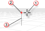
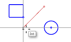
There are two parts of the cursor: the cursor (1) and the marker (2). The cursor always follow the mouse movement.
The marker sometimes leaves the center of the cursor because of some constraint on it such as grid snap or ortho. The marker is a dynamic preview of the point that will be picked when the left mouse button is clicked.
When the marker is constrained, in elevator mode, for example, a tracking line (3) also displays.
Constraints move your marker to a specific point in space or make its movement track according to the constraint so you can model accurately.
Grid snap constrains the marker to an imaginary grid that extends infinitely. You can set the snap spacing to any value.
Click the Grid Snap pane on the status bar to turn grid snap on and off.
Ortho mode constrains the marker movement or object dragging to a specific set of angles. By default, this is parallel to the grid lines, but you can change this. Ortho is similar to the axis lock function found in drawing or animation programs.
Click the Ortho pane on the status bar to turn ortho on and off. Press and hold the Shift key to temporarily toggle the ortho mode.
Another common use for ortho is to constrain object dragging to a specific axis.
Ortho is active after the first point for a command. For example, after picking the first point for a line, the second point is constrained to the ortho angle.
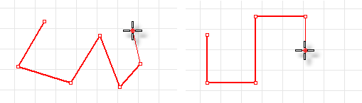
Ortho off (left); Ortho on (right).
If you only need a different angle for a single operation, angle constraint is faster to use. Enter a specific angle for one operation instead of changing the ortho angle and then changing it back.
Object snaps constrain the marker to specific points on an object. When Rhino asks you to specify a point, you can constrain the marker to specific parts of existing geometry. When an object snap is active, moving the cursor near a specified point on an object causes the marker to jump to that point.
Object snaps can persist from pick to pick, or can be activated for one pick only. Multiple persistent object snaps can be set from the status bar. All object snaps behave similarly, but snap to different parts of existing geometry. In addition, there are special object snaps that work for one pick only.
Use persistent objects snaps to maintain an object snap through choosing several points. Since persistent object snaps are easy to turn on and off, you can set them and leave them on until they get in your way. You can then set a different one or just disable them.
Sometimes object snaps interfere with each other and with grid snap or ortho. Object snaps normally take precedence over grid snap or other constraints.
There are other situations where object snaps work in conjunction with other constraints. You will see examples of this in this chapter. For more information including video demonstrations, see the Rhino help topic Object snaps.
The Osnap panel
The Osnap panel is usually located at the left of the screen.
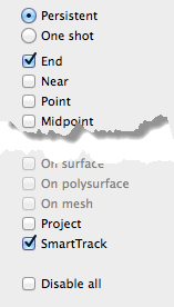
| 4 | Click a check box to turn on an object snap. |
| 4 | Right click a check box to turn an object snap on and turn off all other object snaps. |
| 4 | When an object snap is active, moving the cursor near an eligible point on an object causes the marker to jump to that point and a tooltip to appear. The check boxes in the Osnap panel allow single-use overrides for the persistent object snaps. |
To suspend all persistent object snaps
| 4 | In the Osnap panel, click the Disable all button. All persistent object snaps will be suspended, but remain checked. |
To clear all persistent object snaps
| 4 | In the Osnap panel, click Disable all with the right mouse button. All persistent object snaps will be cleared. |
To turn on one object snap and turn all others off with one click
| 4 | In the Osnap panel, right-click the object snap you want to turn on. |
Complex object snaps that allow selecting multiple reference points or add other advanced controls. See the Rhino help topic Object snaps for more information.
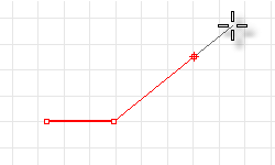
When entering points, you can constrain the marker to a distance or angle from the previous point. Once you have set the distance, drag the line around to any angle. You can also use further snaps to point the line in a specific direction.
During any command that requires two points, such as the Line command, place the first point. Then at the next prompt, type a distance and press Enter.
The marker will be constrained to the specified distance from the previous point. Drag the cursor around the first point and then pick a point.
Angle constraint is similar to ortho, but you can set any angle and it is a one-time setting.
The < symbol is used because it is similar to the symbol used in geometry to indicate an angle.
The marker will be constrained to lines radiating from the previous point separated by the specified angle, where the first line is the specified number of degrees counterclockwise from the x-axis. If you enter a negative number, the angle will be clockwise from the x-axis.
Distance and angle constraints can be used at the same time.
| 1. | In the Value box, type the distance, and press Return. |
| 2. | In the Value box, type the < character and the angle value, and press Return. The order of the distance and angle does not matter. The marker will drag around your original point at angle increments at the specified distance. |
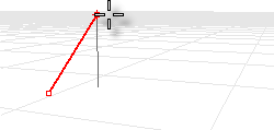
Pick a second point to specify the z-coordinate of the desired point. It is easiest to see this in a different viewport or use the Perspective viewport. Drag the mouse cursor around to see the marker move vertically from the base point along the tracking line.
Pick the point with the mouse or type the height above the construction plane. Positive numbers are above the construction plane; negative numbers are below it. You can use further constraints like coordinates, object snaps or grid snap for the first point, and you can use object snaps for the height.
To move the marker in the construction plane z-direction, hold the Command ⌘ key and click a point on the construction plane, and then drag vertically from the construction plane and click to pick a point.
This constraint is called elevator mode. Using elevator mode to move your pick point vertically from the construction plane lets you work more in the Perspective viewport.
SmartTrack is a system of temporary reference lines and points that is drawn in the Rhino viewport using implicit relationships among various 3-D points, other geometry in space, and the coordinate axes directions.
Temporary infinite lines (tracking lines) and points (smart points) are available to object snaps very much like real lines and points.
You can snap to intersections of the tracking lines, perpendiculars, and directly to smart points as well as intersections of tracking lines and real curves. The tracking lines and smart points are displayed for the duration of a command.
Rhino uses two coordinate systems: construction plane coordinates and world coordinates. World coordinates are fixed in space. Construction plane coordinates are defined for each viewport.
When Rhino prompts you for a point, if you type x and y Cartesian coordinates, the point will lie on the construction plane of the current viewport. For more information about coordinate systems and numeric constraints, see www.mathopenref.com/coordinates.
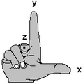
Rhino follows what is called the right-hand rule. The right-hand rule can help you determine the direction of the z-axis. Form a right angle with the thumb and forefinger of your right hand. When your thumb points in the positive x-direction, your forefinger points in the positive y-direction, and the palm of your hand faces in the positive z-direction.
Rhino contains one world coordinate system. The world coordinate system cannot be changed. When Rhino prompts you for a point, you can type coordinates in the world coordinate system.
The arrow icon in the lower left corner of each viewport displays the direction of the world x-, y-, and z-axes. The arrows move to show the orientation of the world axes when you rotate a view.

Each viewport has a construction plane. A construction plane is like a tabletop that the cursor moves on unless you use coordinate input, elevator mode, or object snaps or a few other instances where input is constrained. The construction plane has an origin, x- and y-axes, and a grid. The construction plane can be set to any orientation. By default, each viewport’s construction plane is independent of those in other viewports.
The construction plane represents the local coordinate system for the viewport and can be different from the world coordinate system.
Rhino’s standard viewports come with construction planes that correspond to the viewport. The default Perspective viewport, however, uses the world Top construction plane, which is the same construction plane that is used in the Top viewport.
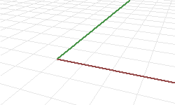
The grid lies on the construction plane. The dark red line represents the construction plane x-axis. The dark green line represents the construction plane y-axis. The red and green lines meet at the construction plane origin.
To change the direction and origin of a construction plane, use the CPlane command. Preset construction planes (World Top, Right, and Front) give you quick access to common construction planes. In addition, you can save and restore named construction planes and import named construction planes from another Rhino file.
2-D construction plane coordinates
| 4 | In a Value box, type the coordinates in the format x,y where x is the x-coordinate and y is the y-coordinate of the point.
|
3-D construction plane coordinates
| 4 | In a Value box, type the coordinates in the format x,y,z where x is the x-coordinate, y is the y-coordinate, and z is the z-coordinate of the point. There are no spaces between the coordinate values. |
| 4 | To place a point 3 units in the x-direction, 4 units in the y-direction, and 10 units in the z-direction from the construction plane origin, type 3,4,10 at the prompt. |
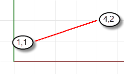
Rhino remembers the last point used, so you can enter the next point relative to it. Relative coordinates are useful for entering a list of points where the relative locations instead of absolute locations of the points are known. Use relative coordinates to locate points according to their relationship to the previous active point.
To use relative coordinates
| 4 | In a Value box, type the coordinates in the format rx,y where r signifies that the coordinate is relative to the previous point. |
For example
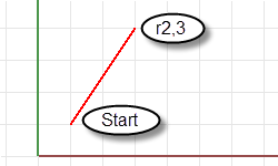
| 1. | Start the Line command. |
| 2. | At the Start of line… prompt, click to place the first end of the line. |
| 3. | At the End of line… prompt, type r2,3, and press Enter. The line is drawn to a point 2 units in the x-direction and 3 units in the y-direction from the last point.
|