 Set up the layers
- In the Layers panel, confirm that the Profile-01 layer is current.
This example shows how to use Rhino to model a simple mechanical part.
You will learn how to:
On the Rhino Help menu, click Learn Rhino, and then click Tutorials and Samples.
In the Tutorials panel, under User's Guide, double-click the tutorial model file Toolblock.3dm.
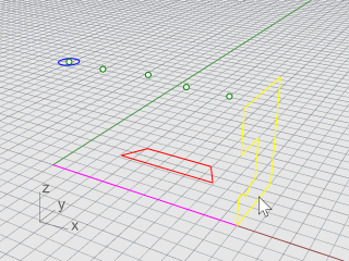
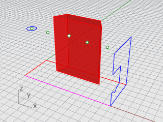
Start by creating two basic solid shapes from the profile curves on layers Profile‑01 and Profile‑02.
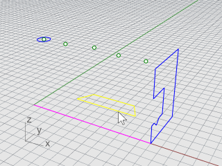
On the Solid menu, click Extrude Planar Curve > Straight.
Turn on the End object snap.
At the Select curves to Extrude prompt, select the blue profile curve, and press Enter.
At the Extrusion distance prompt, set the command-line options Solid=Yes and DeleteInput=No.
Snap to the end of the magenta construction line, and click.
The extruded shape is a solid because it forms a closed volume in space.
Select the red profile curve.
On the Solid menu, click Extrude Planar Curve > Straight.
At the Select curves to Extrude prompt, set the command-line options Solid=Yes and DeleteInput=No.
At the Extrusion distance prompt, in the Front viewport, drag the extrusion above the height of the blue curve and click.
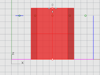
The solid appears on the current red layer Profile-02.
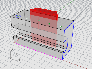
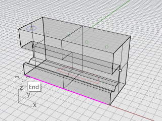
On the Solid menu, click Difference.
At the Select surfaces or polysurfaces to subtract from prompt, select the blue solid, and press Enter.
At the Select surfaces or polysurfaces to subtract with prompt, set the command-line DeleteInput=Yes.
Select the red solid, and press Enter.
The result will be a new solid or polysurface. A polysurface is a collection of surfaces that can be closed or open. A solid is a collection of surfaces that are closed.
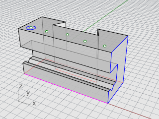
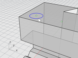
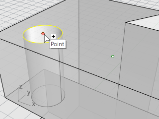
A construction circle is already in place for creating the first hole.
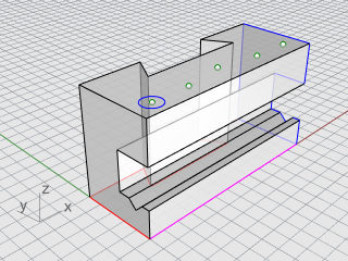
Select the blue circle as shown in the illustration below.
On the Solid menu click Solid Edit Tools > Holes > Make Hole.
At the Select a surface or polysurface prompt, select the gray polysurface.
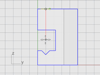
At the Depth point... prompt, drag the hole through the upper portion of the object.
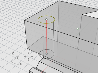
Pick a point in the Right view.
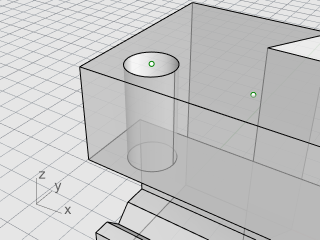
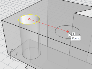
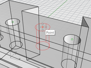
After one hole is drilled, you can copy the others.
In the Osnap control, turn on the Point object snap.
On the Solid menu, click Solid Edit Tools > Holes > Copy Hole.
At the Select holes in one planar surface prompt, select the first hole, and press Enter.
At the Point to copy from prompt, snap to the point object in the center of the first circle, and click.
At the Point to copy to... prompt, snap to the next point that makes the center of the next hole, and click.
Repeat this for the two holes that are on the other side of the part.
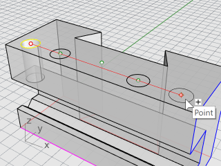
Do not use the point in the center of the part.
The center hole does not pass entirely through the upper part of the blue solid. There is no reference circle to start from.
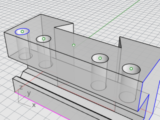
On the Solid menu, click Solid Edit Tools > Holes > Round Hole.
At the Select target surface prompt, select the top surface of the gray solid.
At the Center point prompt, set the command-line options as below:
Depth=0.5
Diameter=0.312 (Note: If the option shows Radius, click Radius to change it to Diameter.)
DrillPointAngle=180
Through=No
Direction=CPlaneNormal
Snap to the point object in the middle of the gray solid to finish creating the hole.
The resulting polysurface is a closed solid. A solid defines a closed volume in space. Object properties will report if this part is a closed solid.
Select the part.
On the Edit menu, click Object Properties (F3).
In the Properties panel, click Details.
In the Object Description window, you will find the listing to confirm that the object is valid and closed.
Geometry:
Valid polysurface.
Closed solid polysurface with 23 surfaces.
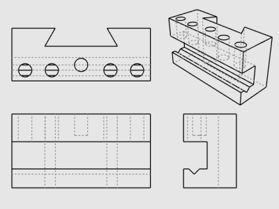
The Make2D command generates 2-D lines from the 3‑D solid.
Select the part.
On the Dimension menu, click Make 2-D Drawing.
In the 2-D Drawing Options dialog box:
Under Projection, select Third angle projection.
Under Options, select By output layers, and check the Tangent edges and Hidden lines boxes.
Click OK.
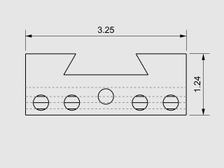
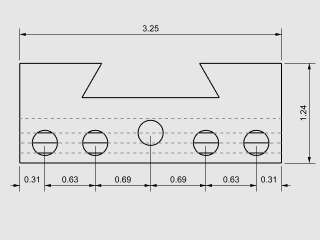
Using the 2-D drawing, add dimensions to the part.
On the Dimension menu, click Linear Dimension.
In the Osnap control, turn on the End object snap; turn off the Point object snap.
At the First dimension point prompt, pick the upper left corner of the part.
At the Second dimension point prompt, pick the upper right corner of the part.
At the Dimension location prompt, pick a location for the dimension line.
Repeat to generate a vertical dimension on the right side of the part.
On the Dimension click Linear Dimension.
At the First dimension point, set the command-line option Continue=Yes.
This will generate a chain of dimensions.
Tip: If the current dimension continues a previous dimension, click the NewChain option.
At the First dimension point prompt, snap to the lower left corner of the part with the End object snap, and click.
At the Second dimension point prompt, snap to the center of the first circle with the Cen object snap, and click.
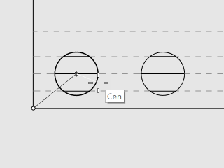
At the Dimension location prompt, pick below the part.
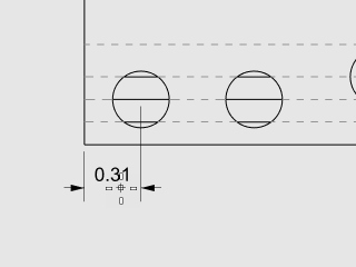
At the next Dimension location prompts, continue picking the centers of the circles.
Finish by picking the lower right corner of the part, and press Enter.
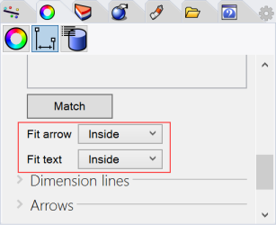
Note: If the dimension text and arrows do not fit inside the dimension lines, you can fix this later in the dimension Properties. Dimension properties let you specify the location of the text and arrows.
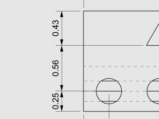
Repeat the chain dimensions to create vertical dimensions.
Click the NewChain option to start dimensioning.
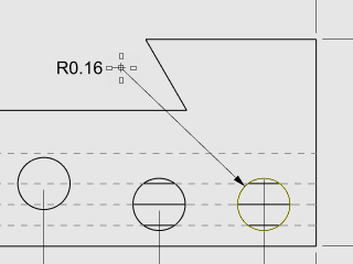
On the Dimension menu, click Radial Dimension.
At the Select curve for radius dimension prompt, select the circle on the far right.
At the Dimension location prompt, pick above the part.
Double-click the radial dimension text, and in the text edit box, add the text:
Typ. 5 Places.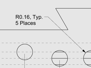
Rhino for Windows © 2010-2018 Robert McNeel & Associates. 24-Nov-2021