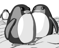
Rendered with Penguin renderer by Jari Saarinen.
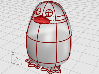
This tutorial demonstrates point-editing techniques including moving and scaling control points and adding knots to surfaces to increase control. In addition, you will use blends to create smooth transitions between surfaces.
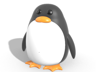
Rendered with Penguin renderer by Jari Saarinen.
You will learn how to:
On the Rhino Help menu, click Learn Rhino, and then click Tutorials and Samples.
In the Tutorials panel, under User's Guide, double-click the tutorial model file Penguin.3dm.
You can open the example model, Penguin.3dm, and try to match the shapes of the complete penguin on the hidden Complete layer as you are building the model. You can experiment with your own shapes, too.
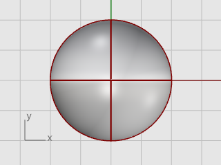
The body and head are created from one sphere. The shape is formed by moving the control points in the sphere to create the head.
On the Solid menu, click Sphere > Center, Radius.
At the Center of sphere... prompt, move the mouse cursor to the Top viewport.
Type 0, and press Enter.
The center of the sphere is placed at the construction plane origin (0,0,0).
At the Radius... prompt, type 10, and press Enter.
A sphere with a radius of 10 units is created.
Use the Rebuild command to add more control points to the sphere.
On the Edit menu, click Rebuild.
At the Select curves, extrusions or surfaces to rebuild prompt, select the sphere, and press Enter.
In the Rebuild Surface dialog box, set the Point count in the U and V directions to 8, and the Degree in the U and V directions to 3.
Check Delete input, and click OK.
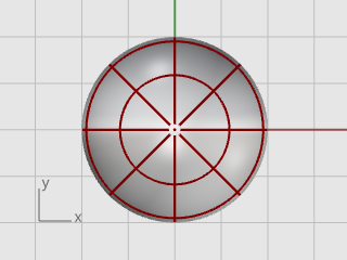
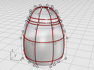
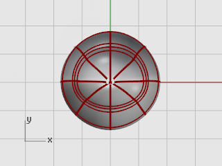
Use the PointsOn command or press F10 to turn on the sphere’s control points.
Look in all the viewports at the structure of the control points.
The next step will change this structure so that moving the control points does not influence the whole sphere.
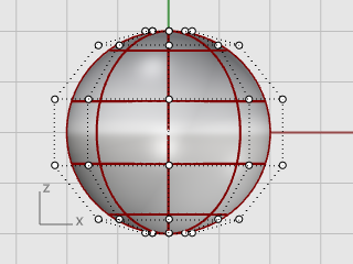
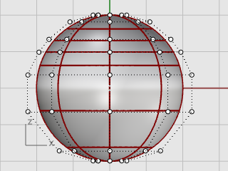
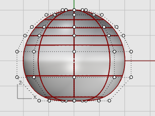
Use the InsertKnot command to insert two knots in the sphere in the area where you want the neck.
On the Edit menu, click Control Points > Insert Knot.
At the Select the curve or surface for knot insertion prompt, select the sphere.
At the Point on surface to add knot prompts, set the command option Direction=U.
Click on the sphere to insert two knots (isocurves) in the u‑direction only.
Examine the control point structure after inserting the knot.
You will reposition control points to create the indentation for the neck and to reform the body shape.
In the Front viewport, window-select the control points near the bottom of the sphere.
On the Transform menu, click Set XYZ Coordinates.
In the Set Points dialog box, check the Set Z, clear the Set X and Set Y check boxes, select Align to World, and click OK.
Drag the selected control points up, and click.
This will align all of the selected control points to the same z-value (up in the Front viewport), flattening the surface.
Window-select the top rows of control points in the Front viewport.
Click the Gumball pane on the status bar to turn it on.
Drag the green arrow of the Gumball widget to move the control points up to shape the body.
For more information about using Rhino's gumball feature, review the Help topic for the Gumball command.
Two video tutorials also help with learning to use the gumball
Hello Gumball! (https://vimeo.com/84954262)
Gumball Advanced (https://vimeo.com/260472052)
In the Perspective viewport, hold the Shift key and drag the Gumball scale handle (the small blue rectangle).
The control points are scaled in two directions.
Look at different viewports to see the changes in the body shape as you move the control points closer to and farther from the center.
Match the example model or use your own shape.
Drag the Gumball scale handle without holding the Shift key.
The control points are scaled in one direction. Make the body slightly flatter in the front and back direction near the head.
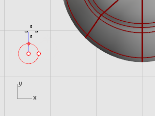
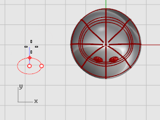
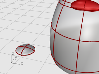
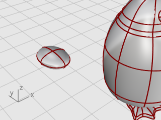
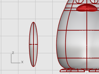
The eye is an ellipsoid shape that is oriented onto the surface.
Start the Ellipsoid command.
At the End of first axis prompt, type 1.1, and press Enter.
This constrains the distance from the center point to the end of the axis to 1.1 units.
Drag the cursor to the right and pick.
At the End of second axis prompt, type 1.1, and press Enter to constrain the distance.
Using these constraints will create a circular ellipsoid when it is seen from the top.
Drag the cursor up or down in the Top viewport and pick.
At the End of third axis prompt, type 0.5, and press Enter.
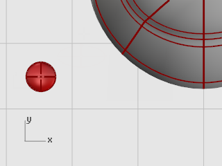
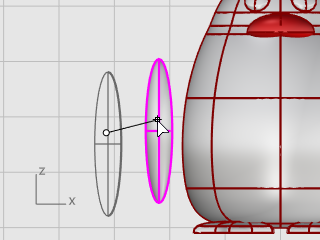
Select the eye ellipsoid in the Top or Perspective viewport.
On the Transform menu, click Orient > On Surface to start the OrientOnSrf command.
At the Base point... prompt, in the Top viewport, pick the center of the ellipsoid.

At the Reference point for scaling and rotation prompt, pick any point to the right or left of the eye ellipsoid.
The exact location is not important.
At the Surface to orient on prompt, select the penguin body.
In the Orient on Surface dialog box, click OK.
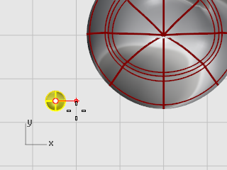
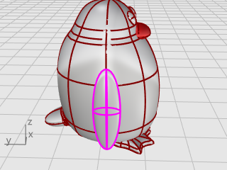
At the Point on surface to orient to… prompt, move the cursor onto the head area where you want to place the eye and click.
Start the Mirror command.
In the Front viewport, at the Start of mirror plane... prompt, type 0, and press Enter.
At the End of mirror plane... move the mouse cursor along the y‑axis with Ortho mode and click.
The second eye is created.
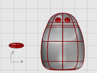
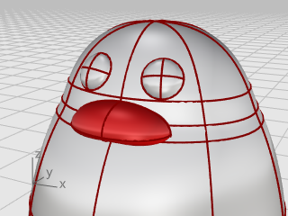
The beak is another ellipsoid that you can edit to change the shape.
Start the Ellipsoid command.
At the End of first axis prompt, type 3, and press Enter.
This constrains the distance from the center point to the end of the axis to three units.
Hold the Shift key, drag the cursor to the right, and pick.

At the End of second axis prompt, type 2, and press Enter.
Using these constraints creates a circular ellipsoid when it is seen from the top.
Drag the cursor up or down in the Top viewport and pick.
At the End of third axis prompt, type 1, and press Enter.
Select the beak and press F10 to turn on the beak's control points.
In the Front viewport, window-select the upper row of points.
Drag the selected points up.
Window-select the middle points of the lower rows.
Drag the control points up to shape the beak.
Tip: You can also try the Nudge keys (Alt + Arrow direction keys) to nudge the selected points.
Move the beak into position using Gumball.
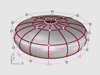
The feet are created using another ellipsoid. Knots are added to help create the webbed toes.
In the Front viewport, start the Ellipsoid command.
Place the center point anywhere.
At the End of first axis prompt, type 1, and press Enter.
This constrains the distance from the center point to the end of the axis to one unit.
With Ortho on, drag the cursor up, and pick.
At the End of second axis prompt, type 3, and press Enter.
In the Top viewport, with Ortho on, drag the cursor up, and pick.
At the End of third axis prompt, type 3, and press Enter.
Use the Rebuild command to add more control points to the ellipsoid.
In the Rebuild Surface dialog box, set the Point count in the U and V directions to 8.
Set the Degree in the U and V directions to 3.
Check Delete input, and click OK.
Select the ellipsoid and start the InsertKnot command.
Set the options to Symmetrical=On and Direction=V.
Insert four knots (isocurves) in the ellipsoid as illustrated, and press Enter.
Windows-select the control points on both top and bottom of the ellipsoid as illustrated.
Hold the Alt key to avoid moving control points.
Hold the Shift key to add more control points to the selection.
Start the Scale2D command, and in the Top viewport, pick the center point with the Point object snap as the Base point.
Pick another point away from the ellipsoid as the First reference point.
Drag the points to make the whole foot about twice the size of the original ellipsoid and click.
Use Gumball to move the foot in the Top and Front viewports under the penguin body.
Select the foot in the Top viewport.
Click Gumball's blue rotation control, type -15, and press Enter to rotate the foot 15 degrees.
Select the foot and start the Mirror command in the Front viewport.
Type 0, and press Enter to place the start of the mirror plane at the construction plane origin.
Hold the Shift key to enable Ortho mode, drag the mouse cursor up or down, and click.
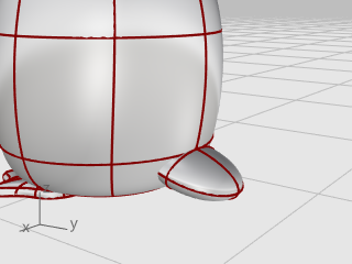
Select the feet, on the Surface menu, click Plane > Cutting Plane.
In the Front viewport, pick two points to make a planar surface that passes through the feet as illustrated.
Hold the Shift key to enable Ortho mode while picking the second point.
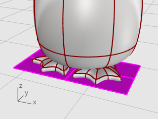
Trim the bottoms of the feet off with the plane as the cutting object.
Select the feet and the cutting plane.
On the Edit menu, click Trim.
In the Front viewport, click the three positions as illustrated, and press Enter.
While the remaining surfaces are still selected, on the Edit menu, click Join.
The surfaces are joined into two closed polysurfaces.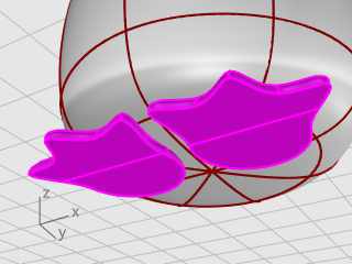
The tail is another ellipsoid. It is joined to the body with a smooth blend surface.
Draw an Ellipsoid.
First axis: 4 units (Y in Top view).
Second axis: 3 units (X in Top view)
Third axis: 1.5 units (Y in Front view).
Use Gumball to Move and Rotate the tail into position.

Combine the tail and the body shapes with a Boolean operation.
On the Solid menu, click Union.
At the Select surfaces or polysurfaces to union prompt, click the tail and the body, and press Enter.
The tail and body are combined into a single object.
The transition between the tail and body is rather abrupt; so replace this with a smooth blend surface.
On the Solid menu, click Fillet Edge > Blend Edge.
At the Select edges to blend... prompt, type 0.6, and press Enter.
The NextRadius option is set to 0.6 units.
Pick the edge between the tail and body, and press Enter twice.
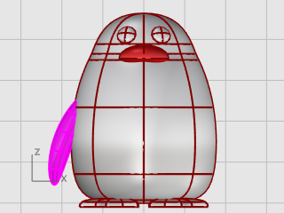
Draw an Ellipsoid.
First axis: 6.5 units (Y in Front view).
Second axis: 1.2 units (X in Front view)
Third axis: 2 units (Y in Top view).
Move the ellipsoid close to the body in the Front viewport.
At the Start of spine prompt, in the Front viewport, pick near the bottom of the wing ellipsoid.
At the End of spine prompt, pick near the top of the wing.
At the Point to bend through… prompt, drag the top of the wing toward the body to intersect.
If further positioning is required, use Gumball to place the wing.
Use the Mirror command to create the opposite wing.
Select the body and wings.
On the Solid menu, click Union.
The body and wings are trimmed by each other and joined into a single object.
To finish the penguin, split the front part of the body so a different material can be applied to it.
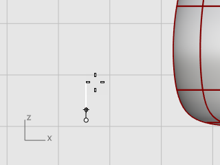
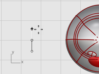
Draw a curve from the beak down to the bottom.
On the Curve menu, click Free-Form > Interpolate Curve.
In the Right viewport, pick three points as illustrated, and press Enter.
Split the body surface with the curve. This allows a different material for the front of the body.
On the Edit menu, click Split.
At Select object to split... prompt, select the body, and press Enter.
At Select cutting objects... prompt, select the curve, and press Enter.
To produce a realistic rendering of your model, materials and lighting will be required.
On the Render menu, click Create Point Light.
In the Top viewport, click near the location as illustrated.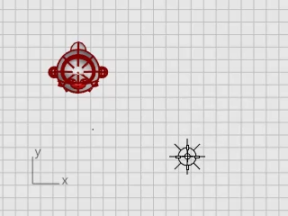
In the Front viewport, move the point light to be higher than the penguin.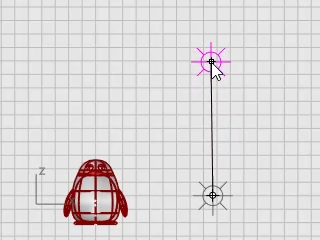
Type Materials and press Enter.
The Materials panel is opened on the right side.
Click the  button, and on the material template list, click Plastic.
Replace the name Plastic with the name Body.
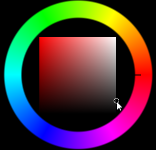
Under Plastic, click the Color swatch to open the Select Color dialog.
Select a dark gray color.
Create three more Plastic materials named Eyes, Beak and Feet, and Belly.
Set the Eyes color to black, the Beak and Feet color to orange, and the Belly color to white.
Make the Perspective viewport current, on the View menu, click Rendered.
Drag the Body material from the Material panel, and drop it onto the penguin body.
The material is assigned to a single object.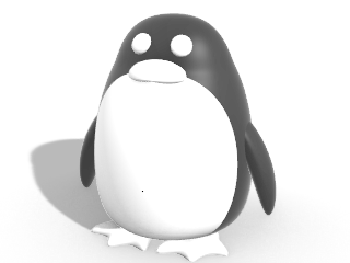
Drag the Belly material from the Material panel, and drop it onto the front part of the penguin.
Select the beak and feet.
Select the eyes.
Rhino for Windows © 2010-2018 Robert McNeel & Associates. 24-Nov-2021