This tutorial demonstrates how to create surfaces from profile curves.
You will learn how to:
On the Rhino Help menu, click Learn Rhino, and then click Tutorials and Samples.
In the Tutorials panel, under User's Guide, double-click the tutorial model file Headphone.3dm.
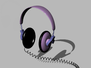
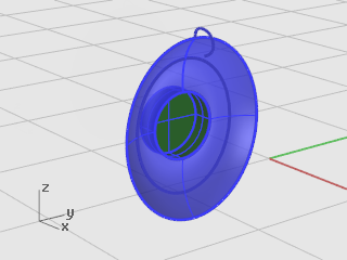
The speaker shell is created using a lofted surface, a one-rail sweep, a solid extrusion of a planar curve, and a surface fillet. The resulting geometry is joined into one solid.
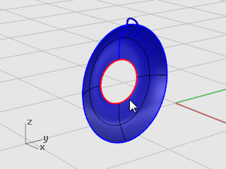
One way to create a surface is to use existing curves as a guide. When lofting through curves, the curves are used as a guide for creating a smooth surface.
Right-click on the Perspective viewport title, and on the viewport title menu, click Shaded.
The Perspective viewport is now in the Shaded display mode.
Select the three circular curves, with a crossing selection as illustrated. 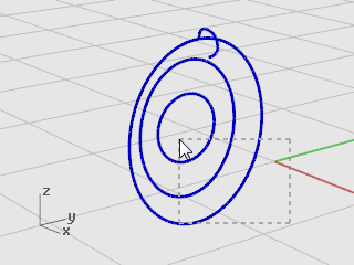
On the Surface menu, click Loft.
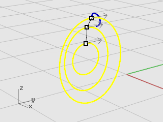
At the Drag seam point to adjust… prompt, note the display of the curve direction arrows at the seam points.
In this model, they are nicely lined up, so you do not need to adjust them.
Press Enter.
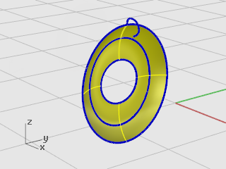
In the Loft Options dialog box, click OK to create the loft.
Hold down Ctrl and Shift, and click to select individual object features such as:
This action is called sub-object selection.
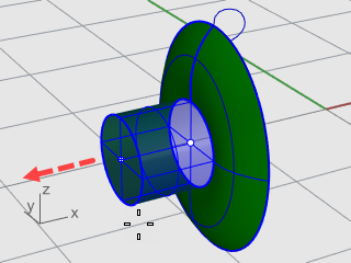
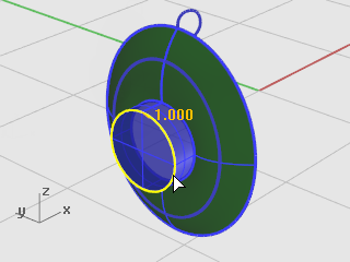
Extrude the lofted surface edge in the center to make a magnet housing on the convex side of the speaker shell.
Hold down Ctrl and Shift to select the surface edge at the center of the lofted surface.
On the Solid menu, click Extrude Planar Curve > Straight.
At the Extrusion Distance… prompt, move the cursor to the convex side, type 2, and press Enter.
This makes a solid cylinder for the magnet housing that is two units thick and extends from the original surface edge.
Note: The cylinder you just created is an extrusion object (solid). The housing cylinder needs to be open on the bottom.
In the next step, you will use sub-object selection to remove the bottom face.
Hold down Ctrl and Shift, and click to select the bottom face.
Press the Delete key.
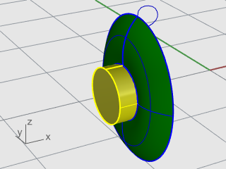
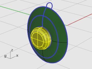
On the Solid menu, click Fillet Edge > Fillet Edge.
The current NextRadius setting should be 1.
At the Select edges to fillet… prompt, select the edge at the top of the cylinder, and press Enter.
At the Select fillet handle to edit... prompt, press Enter.
Surfaces that share an edge can be joined into a polysurface.
In the next step, you will join all the surfaces.
Select the surface and the polysurface.
On the Edit menu, click Join.
To join surfaces, you must select surfaces that are adjacent to each other and the edges must match.
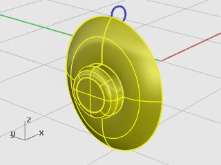
Sweep a curve around the edge of the speaker cone to create the padding around the edge of the speaker.
On the View menu, click Zoom > Zoom Extents All.
All viewports are zoomed in or out to show all the objects.
On the Surface menu, click Sweep 1 Rail.
At the Select rail prompt, select the loft surface outer edge.
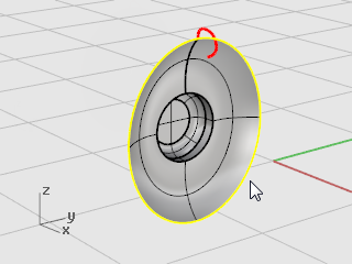
At the Select cross section curves prompt, select the cross section curve at the top of the speaker as shown, and press Enter.
In the Sweep 1 Rail Options dialog box, enable Refit rail, and click OK.
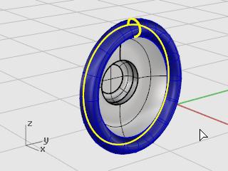
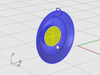
Hold down Ctrl and Shift, and click to select the inner edge of the padding as illustrated.
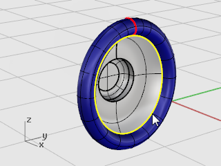
On the Surface menu, click Planar Curves.
A planar surface is created at the base of the padding.
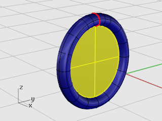
This fills the area at the base of the padding with a planar surface created from the edge of the sweep.
The next part is the bracket that holds the speaker to the headband. Since the speaker unit is complete, you can turn its layer off and make the Bracket layer current.
On the status bar, click the Layer pane where it shows Speaker.
Make Bracket the current layer, and turn on the layer Bracket Shape Curves.
Turn all other layers off.
Select the closed curve.
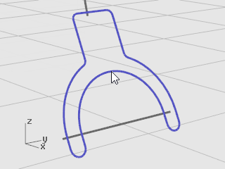
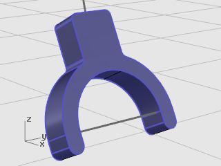
On the Solid menu, click Extrude Planar Curve > Straight.
At the Extrusion distance… prompt, move the cursor to the left, type 1, and press Enter.
On the Solid menu, click Fillet Edge > Fillet Edge.
At the Select edges to fillet… prompt, type 0.2, and press Enter.
At the Select edges to fillet… prompt, click ChainEdges, and select the front edge of the bracket.
The entire edge of the solid should highlight.
Press Enter to close that edge selection.

At the Select edges to fillet… prompt, click ChainEdges, and select the back edge of the bracket.
Press Enter to close that edge selection.
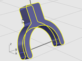
Press Enter to finish the edge selection.
At the Select fillet handle to edit... prompt, press Enter.
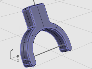
This rounds all of the sharp edges.
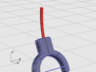
Select the curve at the top of the bracket.
On the Solid menu, click Pipe.
At the Start radius… prompt, set the command-line options to Cap=Flat and Thick=No.
Type 0.3, and press Enter.
At the End radius… prompt, press Enter.
At the Point for next radius... prompt, press Enter.
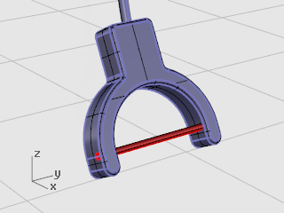
Select the curve at the bottom of the bracket.
On the Solid menu, click Pipe.
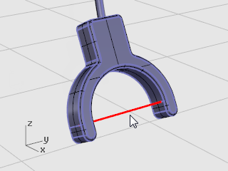
At the Start radius… prompt, type 0.2, and press Enter.
At the End radius… prompt, press Enter.
At the Point for next radius... prompt, press Enter.
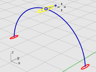
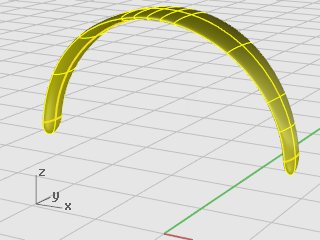
The headband consists of a series of ellipses swept along a path.
On the status bar, click the Layer pane.
Make Headband the current layer, and turn on the layer Headband Shape Curves.
Turn all other layers off.
On the View menu, click Zoom > Zoom Extents All to zoom in on the headband shape curves in all viewports.
Turn Ortho on.
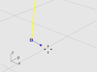
On the Curve menu, click Ellipse > From Center.
At the Ellipse center… prompt, click AroundCurve.
Select the curve.
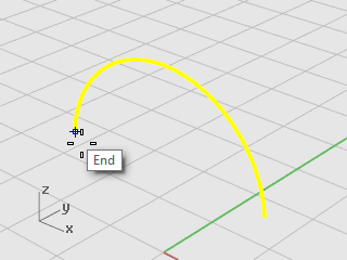
At the Center of ellipse prompt, snap to an endpoint of the headband curve and click.
Use the End object snap.
At the End of first axis prompt, type 0.5, and press Enter.
At the End of first axis prompt, drag the cursor in the x‑direction and click.
At the End of second axis prompt, type 2, and press Enter.
At the End of second axis prompt, drag the cursor in the y‑direction and click.
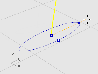
Select the ellipse.
On the Transform menu, click Array > Along Curve.
At the Select path curve prompt, select the headband curve.
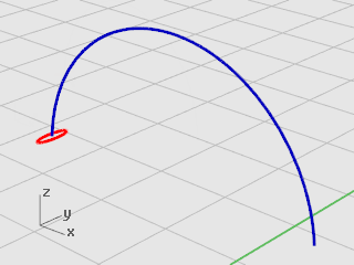
In the Array Along Curve Options dialog box, under Method, set the Number of items to 3.
Under Orientation, click Freeform, and click OK.
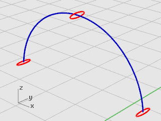
Select the center ellipse.

On the Transform menu, click Scale > Scale 1‑D.
Scale1D stretches an object in one direction.
At the Base point… prompt, press Enter.
At the Scale factor or first reference point… prompt, type 2, and press Enter.
At the Scale direction… prompt, drag the cursor in the y‑direction and click.
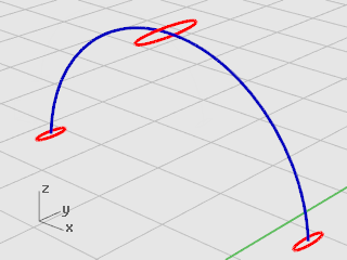
This makes the center ellipse larger.
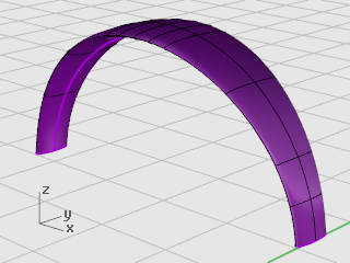
On the Surface menu, click Sweep 1 Rail.
At the Select rail prompt, select the headband curve.
At the Select cross section curves prompt select the three ellipses, and press Enter.

At the Drag seam point to adjust… prompt, examine the direction and seam points of the curves to make sure they are not twisted, and press Enter.
In the Sweep 1 Rail Options dialog box, click OK.
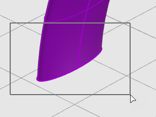
Use the same ellipse that formed the first cross-section curve for the headband to create a rounded end for the headband. Start by splitting the ellipse in half.
On the View menu, click Zoom > Zoom Window.
In the Perspective viewport, drag a rectangle to enclose the left end of the headband to zoom in.
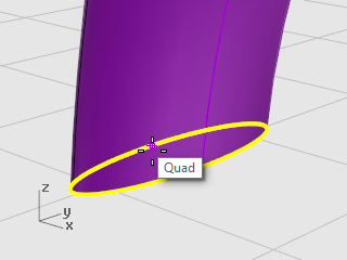
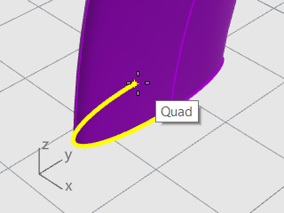
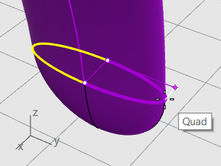
In the Object Snap control, right-click the Quad object snap.
The Quadrant object snap is enabled. All the others are disabled at the same time.
On the Edit menu, click Split.
At the Select objects to split… prompt, click the Point option.
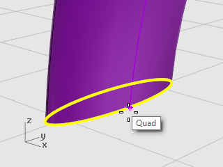
At the Select curve to split prompt, select the ellipse.
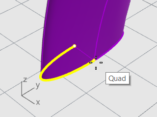
At the Point to split curve prompts, snap to the two quadrants at the narrow axis of the ellipse and click, and then press Enter.
The ellipse is split into two halves.
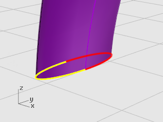
Select the left half of the ellipse.
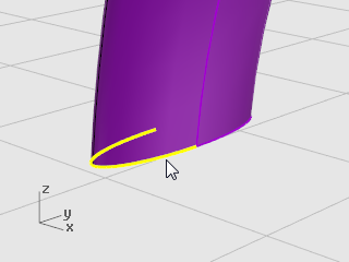
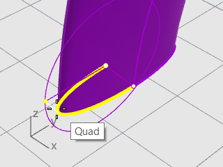
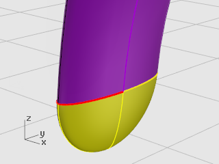
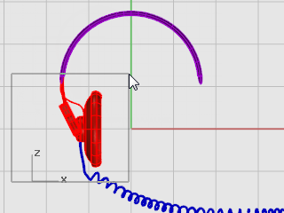
On the Surface menu, click Revolve.
At the Start of revolve axis prompt, snap to the end of the ellipse half and click.
At the End of revolve axis prompt, snap to the other end of the ellipse half and click.
At the Start angle... prompt, snap to the ellipse at the outer edge of the headband and click.
At the Revolution angle... prompt, rotate the view to see the other side.
Swing the mouse cursor down and snap to the other side of the ellipse and click.
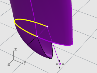
A rounded surface is created at the end of the headband.
Select the rounded end. 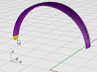
On the Transform menu, click Mirror.
At the Start of the mirror plane prompt, type 0, and press Enter.
At the End of the mirror plane prompt, drag the mirror line in the y‑direction as illustrated, and click.
Hold down Shift to help move the cursor in the ortho direction.
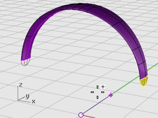
Select the surfaces.
On the Edit menu, click Join.
Three surfaces are joined into one polysurface.
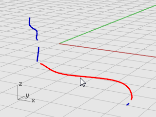
Use a separate layer to create the speaker wire.
On the status bar, click the Layer pane.
Make Wire Shape Curves the current layer and turn on the layer Wire.
Turn all other layers off.
On the View menu, click Zoom > Zoom Extents All.
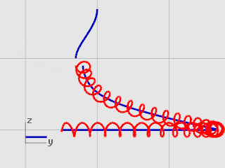
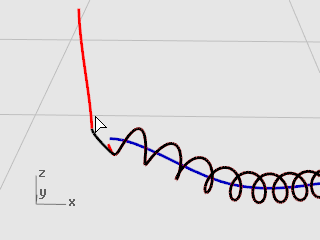
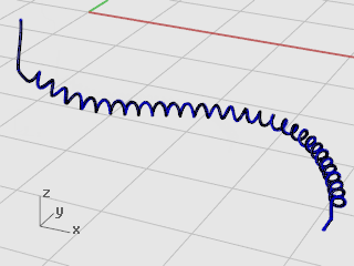
On the Curve menu, click Helix.
At the Start of axis… prompt, click AroundCurve.
At the Select curve prompt, select the long free-form curve.
At the Radius and start point… prompt, type 1, and press Enter.
This sets the radius for the helix.
At the Radius and start point… prompt, set Turns=30 and NumPointsPerTurn=8.
At the Radius and start point… prompt, in the Right viewport drag the cursor to the left and click.
Hold down Shift to help move the cursor in the ortho direction.
On the View menu, click Zoom > Window.
In the Perspective viewport, zoom in on the left end of the helix you just created.
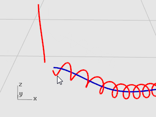
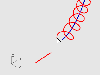
On the Solid menu, click Pipe.
At the Select rail prompt, select the extended helical curve.
At the Start radius… prompt, type 0.2, and press Enter.
At the End radius… prompt, press Enter.
At the Point for next radius prompt, press Enter.
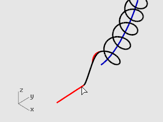
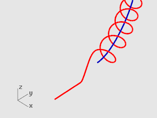
Select the curve at the top left.
On the Solid menu, click Pipe.
At the Start radius… prompt, type 0.1, and press Enter.
At the End radius… prompt, press Enter.
At the Point for next radius prompt, press Enter. 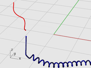
Mirror the parts to create the parts for the other side of the headphones.
On the status bar, click the Layer pane.
Turn on all layers.
On the View menu, click Zoom > Zoom Extents All.
Press Esc to deselect anything currently selected.
On the Edit menu, click Select Objects > Curves.
Press the Delete key.
In the Front viewport, window-select the speaker, bracket, small wire, and rotated ellipse as illustrated.
On the Transform menu, click Mirror.
The Mirror command depends on which viewport is active. It uses the construction plane in the active viewport to define the mirror plane. The mirror plane is perpendicular to the construction plane. Two points define the line in this plane about which the selected objects are mirrored.
At the Start of mirror plane prompt, type 0, and press Enter.
This is the first point of the mirror line.
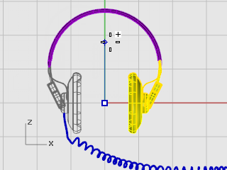
At the End of mirror plane prompt, turn on Ortho, and drag the mirror line straight up and pick.
 Learn more
For a video tutorial showing a more sophisticated modeling method for a headphone set using Rhino's Gumball feature, see: Modeling stereo headphones.
Rhino for Windows © 2010-2018 Robert McNeel & Associates. 24-Nov-2021