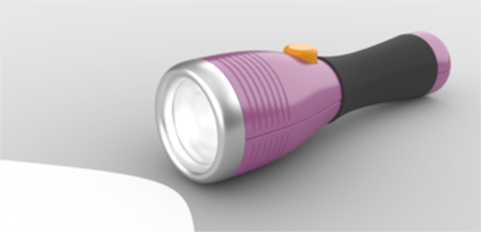
Creating surfaces from curves and joining the surfaces together allows you greater freedom for modeling the shape.
This tutorial introduces the concept of drawing curves and one method of creating surfaces from those curves.
You will learn how to:
You will use guides as a frame of reference for drawing the profile curves of the flashlight.
On the Rhino Help menu, click Learn Rhino, and then click Tutorials and Samples.
In the Tutorials panel, under User's Guide, double-click the tutorial model file Flashlight.3dm.
Guides are infinite construction lines that only display when you are picking a point for a command or when you are dragging objects with an object snap active.
Click anywhere in the Front viewport to make it active and press F7.
This hides the construction plane grid so you can easily see the guides you are going to add.
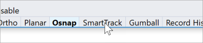
On the status bar, turn on SmartTrack.
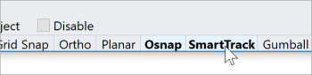
Note: To use guides, SmartTrack and OSnap have to be turned on at the same time.
Type AddGuide, and press Enter.
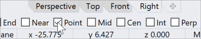
At the Guide base point prompt, in the Object Snap control, right-click on the Point checkbox.
This turns on the Point object snap and turns off all the others.
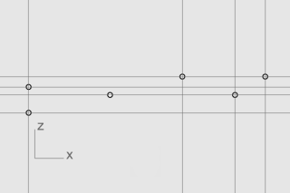
Snap to a point, move the cursor vertically or horizontally, and click to add a guide.
If the cursor cannot move vertically or horizontally, hold down Shift to temporarily enable Ortho mode.
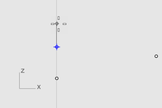
Add more guides as illustrated.
Tip: If a guide is not added properly, use the RemoveGuide command to remove the guide.
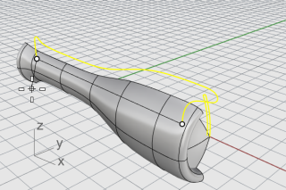
You are going to draw a profile curve that you will use to revolve and create the flashlight body.
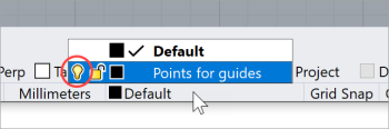
On the status bar, click the Layer pane, and click the light bulb of the Points for guides layer to turn it off.
On the Curve menu, click Free-Form > Control Points.
Set command-line options to Degree=3 and PersistentClose=No.
Note: When guides display, Int and Near object snaps are always turned on.
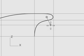
At the Next point... prompt, continue placing points as illustrated. Press Enter when done.
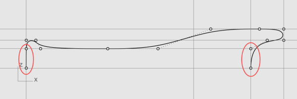
All the points will be placed either on a guide or at an intersection of two guides.
Note: The first and last two points must be placed along the y‑axis so the surface created from the curve will be smooth at both ends.
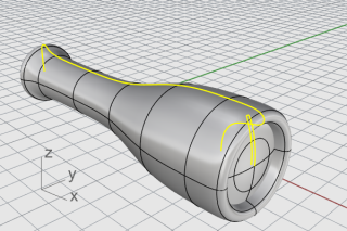
Make another profile curve for the lens.
On the Curve menu, click Free-Form > Control Points.
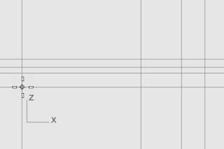
At the Start of curve… prompt, in the Front viewport, hold down Alt and place the first point as illustrated.
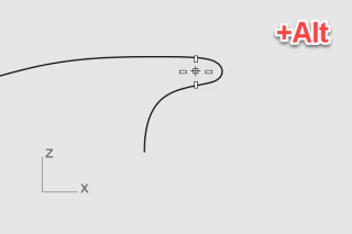
Note: Holding down Alt hides the guides and avoids snapping to the guides.
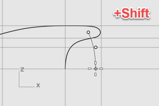
Note: Holding down Shift enables Ortho mode. The second and third points are placed along the y‑axis.
On the status bar, turn SmartTrack off to disable guides.
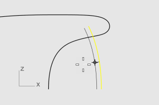
On the Curve menu, click Offset > Offset Curve.
At the Select curve to offset... prompt, set the command-line options
Distance=1.5 and Cap=None.
Select the outer lens profile curve in the Front viewport, move the cursor to the left and click.
On the Curve menu, click Line > Single Line.
In the Object Snap control, check End.
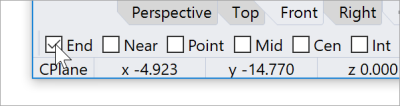
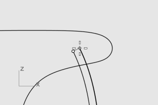
Snap to the upper ends of the lens profile curves.
This creates a line to fill the gap.
Select the line and the lens profile curves.
On the Edit menu, click Join.
The curves and line are joined into a polycurve.
To make the body and lens surfaces, you will revolve the body and lens profile curves 360 degrees. You will use two curve ends to establish the revolve axis.
Right-click on the Perspective viewport title, and select Shaded.
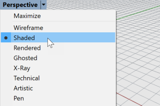
Note: The Shaded display mode uses render meshes to display surfaces so you can see the surfaces when they are created.
Select the body and lens profile curves.
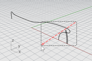
Tip: Drag the cursor from right to left, the dashed rectangle is the crossing selection window. All objects that intersect or are within the rectangle will be selected.
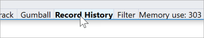
On the status bar, click Record History.
The next command will have History recorded.
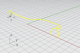
On the Surface menu, click Revolve.
At the Start of revolve axis prompt, snap to an end of the body profile curve and click.
At the End of revolve axis... prompt, snap to the other end and click.
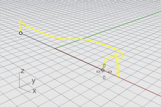
At the command line, click the FullCircle option.
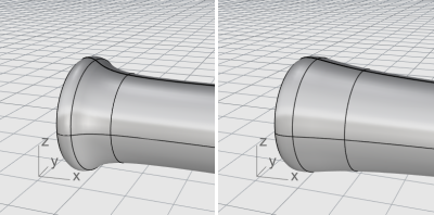
We recorded History when building the flashlight body and lens surfaces. In the next section, we will change the shape of the body profile curve and let History update the body surface.
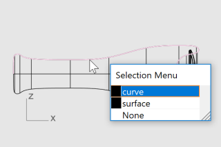
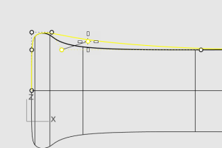
In the Front viewport, select the body profile curve.
The body profile curve and surface are overlapped. The Selection Menu pops up because Rhino cannot tell what you are going to select. You will have to select curve from the list.
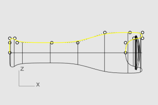
Note: When you select a single curve, its control points turn on automatically. The control points turn off when you deselect the curve. If you need control points to stay on when a curve is deselected, select the curve, and press F10.
Drag the control points to change the shape of the body profile curve.
History updates the body surface for you.
Rhino for Windows © 2010-2018 Robert McNeel & Associates. 24-Nov-2021