
This tutorial demonstrates using solid primitives and simple transforms.
You will learn how to:
When you pick a point with the mouse, the point lies on the construction plane of the active viewport unless you use a modeling aid such as object snap or elevator mode.
When Rhino prompts for a point, you can enter x‑, y‑, and z‑coordinates instead of picking a point. Each viewport has its own construction plane on which its x‑ and y‑coordinates lie. The z‑coordinate for the active viewport is perpendicular to the x‑y plane.
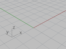
The grid is a visual representation of the construction plane. The intersection of the dark red and green lines is the origin point (x=0, y=0, z=0) of the coordinate system.
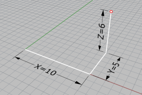
This exercise uses x‑, y‑, and z‑coordinates to place points accurately. When you type the coordinates, type them just as they are shown in this manual. The format is x,y,z. For example, type 10,5,6. You must type commas to separate the numbers. These coordinates place the point at x=10, y=5, and z=6 in the active viewport.
Whenever you type coordinates to place a point, look in all the viewports, so you can get an idea of how coordinate entry works.
On the File menu, click New.
In the Open Template File dialog box, select Small Objects - Centimeters.3dm, and click Open.
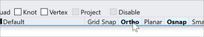
In the status bar, turn Ortho on.
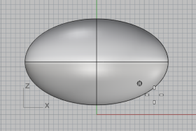
On the Solid menu, click Ellipsoid > From Center.
At the Ellipsoid center… prompt, move the cursor to the Top viewport.
When Rhino prompts for picking a point, moving the cursor to a viewport makes the viewport active/current.
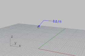
Type 0,0,11, and press Enter.
This places the center point of the ellipsoid at x=0, y=0, and z=11. Look at the point in the Perspective viewport.
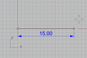
At the End of first axis… prompt, type 15, and press Enter.
Move the cursor to the right to specify the direction and click.
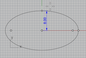
At the End of second axis prompt, type 8, and press Enter.
Move the cursor up to specify the direction and click.
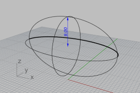
At the End of third axis prompt, type 9, and press Enter.
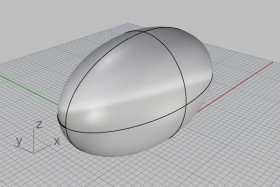
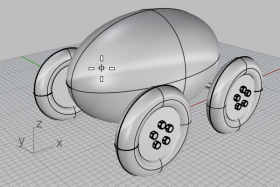
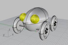
You now have an egg shape that has different dimensions in all three directions.
The axles and wheel hubs are cylinders. The axles are long, thin cylinders, and the wheel hubs are short, fat cylinders. You are going to make one axle and one complete wheel. You will then mirror the complete wheel to the other side. You can then either mirror or copy the complete axle and wheel set to the front of the toy.
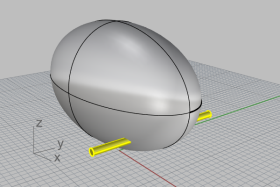
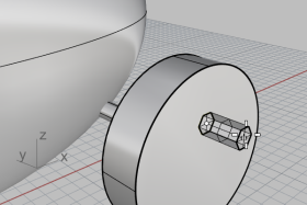
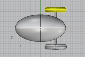
Rotate the perspective viewport so that you are looking along the x‑axis as illustrated.
Turn on Shaded display mode in the Perspective viewport.
On the Solid menu, click Cylinder.
At the Base of cylinder… prompt, move the cursor to the Front viewport.
Type 9,6.5, and press Enter.
When you only type x- and y‑coordinates, the z‑coordinate is automatically 0.
At the Radius… prompt, type 0.5, and press Enter.
At the End of cylinder prompt, at the command line, set BothSides=Yes.
Type 10, and press Enter.
A cylinder 20 centimeters long is created.
On the Solid menu, click Cylinder.
At the Base of cylinder… prompt, move the cursor to the Front viewport, type 9,6.5,10, and press Enter.
At the Radius... prompt, type 4, and press Enter.
At the End of cylinder prompt, set BothSides=No.
Type 2, and press Enter.
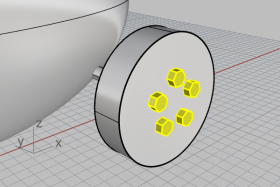
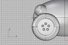
You have created a cylinder that represents a wheel hub.
You will make the lug nuts by extruding a hexagonal polygon curve.
On the Curve menu, click Polygon > Center, Radius.
At the Center of inscribed polygon... prompt, type 6, and press Enter.
This sets the NumSides option to 6.
Move the cursor to the Front viewport, type 9,8,12, and press Enter.
This places the polygon on the surface of the wheel hub.
At the Corner of polygon… prompt, type 0.5, and press Enter.
Move the cursor to the right ,and click to specify the orientation of the hexagon.
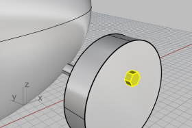
In the Perspective viewport, select the hexagon you just created.
On the Solid menu, click Extrude Planar Curve > Straight.
At the Extrusion distance... prompt, set the command-line options as below:
BothSides=No
Solid=Yes
DeleteInput=Yes
Move the cursor away from the wheel hub.
The extrusion direction in preview defines the positive direction for the next step.
Type 0.5, and press Enter.
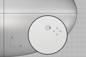
To create the lug nuts on the first wheel, you are going to use a polar (circular) array. An array is a set of copies of an object. A polar array copies the objects around a central point. The objects are rotated as they are copied.
In the Front viewport, select the lug nut.
On the Transform menu, click Array > Polar.
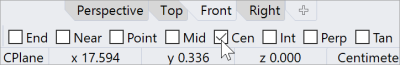
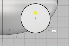
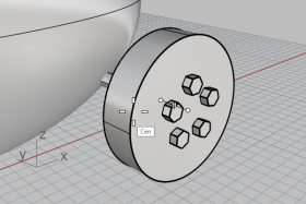
At the Center of polar array... prompt, in the object snap control, check Cen.
Move the cursor near the hub edge to until the cursor snaps to the center of the hub and click.
At the Number of items… prompt, type 5, and press Enter.
At the Angle to fill... prompt, press Enter.
At the Press Enter to accept prompt, preview the result and press Enter.
The tire is a solid form called a torus, which looks like a donut. When you are drawing a torus, the first radius is the radius of a circle around which the “tube” is drawn. The second radius is the radius of the tube itself.
To draw the tire, you will draw the center of the torus tube a bit larger than the diameter of the wheel hub. The tube itself is slightly larger than the hub. This makes it dip into the hub.
On the Solid menu, click Torus.
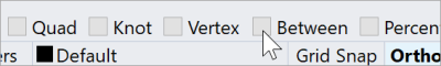
At the Center of torus... prompt, move the cursor to the Object Snap control, hold the Shift key to activate the alternate options, and click Between.
In the Perspective viewport, move the cursor near an edge of the wheel hub until the Cen tooltip appears and click.
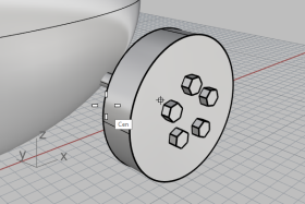
Move the cursor near the other edge until the Cen tooltip appears and click.
This places the center of the torus at the middle of the hub "between" the centers of two circles that make up the edges of the wheel hub.
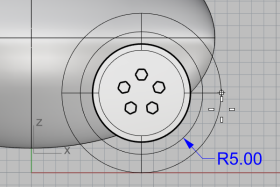
At the Radius… prompt, move the cursor to the Front viewport, type 5, and press Enter.
This makes the radius of the torus tube one unit bigger than the wheel hub.
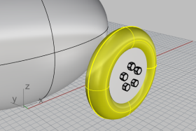
At the Second radius… prompt, type 1.5, and press Enter.
This makes the inner dimension of the torus tube 0.5 units smaller than the wheel hub.
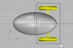
Now that you have a whole wheel with tire created, use the Mirror command to create the other three.
In the Top viewport, window-select the wheel as illustrated.
Be sure to select all the wheel parts.
On the Transform menu, click Mirror.
At the Start of mirror plane… prompt, at the command line, click the XAxis option.
A mirrored copy of the wheel is made across the construction plane x‑axis.
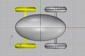
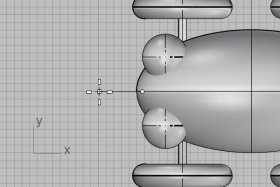
In the Top viewport, window-select the wheels and axle as illustrated.
On the Transform menu, click Mirror, or right-click to repeat the command.
At the Start of mirror plane… prompt, at the command line, click the YAxis option.
A mirrored copy of the wheel set is made across the construction plane y‑axis.
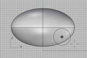
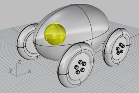
You are going to draw a sphere on the body ellipsoid to represent an eye.
On the Solid menu, click Sphere > Center, Radius.
At the Center of sphere... prompt, move the cursor to the Object Snap control, hold the Ctrl key to activate alternate options, and click OnSrf.
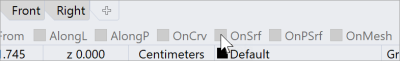
In the Perspective viewport, select the body ellipsoid, and pick a point on the surface as illustrated.
At the Radius… prompt, type 3, and press Enter.
In the Top viewport, select the eye.
On the Transform menu, click Mirror.
At the Start of mirror plane… prompt, type 0 (this is a shortcut for typing 0,0,0), and press Enter.
At the End of mirror plane… prompt, with Ortho on, drag the cursor to the left and click.
A mirrored copy of the eye is created on the opposite side across the x‑axis.
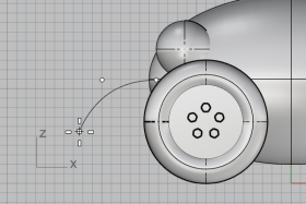
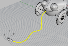
To make the cord, you are going to draw a free-form curve using elevator and planar mode. When the curve is complete, use the Pipe command to make it a thick solid.
Zoom out in all the viewports; you are going to need some space in front of the body ellipsoid to work.
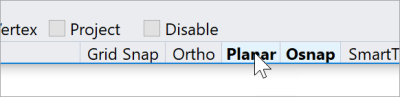
On the status bar, turn Planar mode on, and turn Ortho off.
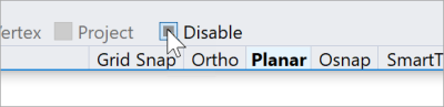
In the Object Snap control, click Disable to turn off all object snaps.
On the Curve menu, click Free-form > Control Points.
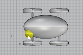
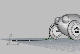
At the Start of curve… prompt, in the Top viewport, hold the Ctrl key and click near and inside the front end of the body ellipsoid.
This only activates the Elevator mode. You have not placed the start point of the curve yet.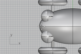
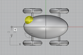
Move the cursor to the Front viewport, drag the cursor upwards near the end of the ellipsoid, and click.
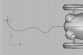
At the Next point… prompt, return to the Top viewport, move the cursor left and click.
Planar mode keeps successive points at the same construction plane elevation. Elevator mode and object snaps override Planar mode. Watch the curve in the Front and Right viewports.
Place the third point in the Front viewport.
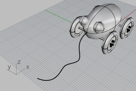
Turn off Planar mode and click several more points in the Top viewport to create a free-form curve. Press Enter when done.
Notice that the points are placed on the Top construction plane.
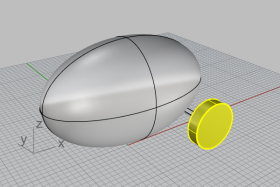
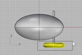
Draw a small Ellipsoid to represent a handle at the end of the curve.
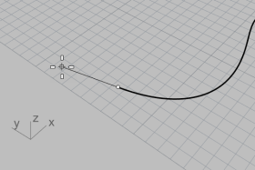
On the Solid menu, pick Ellipsoid > From Foci.
At the First focus... prompt, hold the Alt key and check End object snap.
Holding the Alt key allows accessing object snap checkboxes while Disable is on.
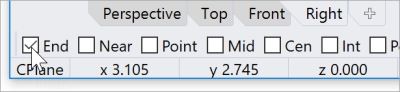
In the Top or Perspective viewport, while holding the Alt key, snap to the end of the cord curve and click.
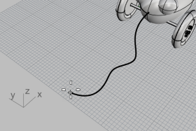
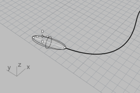
At the Second focus... prompt, drag the cursor along the cord curve direction about 5 units.
You can see the distance you are dragging the cursor from the last point in the status bar.
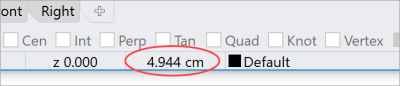
Click to place the second focus point.
Drag the cursor to specify an appropriate size for the handle and click.
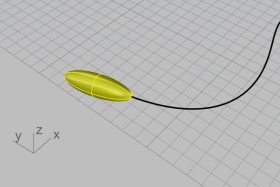
Select the cord curve.
On the Solid menu, click Pipe.
At the Start radius… prompt, type 0.2, and press Enter.
At the End radius… prompt, press Enter.
At the Point for next radius... prompt, press Enter.
The pipe will be the same radius for the full length of the curve.
Rhino for Windows © 2010-2018 Robert McNeel & Associates. 24-Nov-2021