Since Rhino is a mathematically accurate NURBS modeler, it includes tools to provide accurate information about the objects.
Some analysis commands provide information about location, distance, angle between lines, and radius of a curve. For example:
Curves and surfaces have a direction. Many commands that use direction information display direction arrows and give you the opportunity to change (flip) the direction.
Every surface is roughly rectangular. Surfaces have three directions: u, v, and normal.
The u‑ and v‑directions are like the weave of cloth or screen. The u‑direction is indicated by the red arrow, and the v‑direction is indicated by the green arrow. The colors match the grid axis colors. The normal direction is indicated by the white arrow. You can think of u-, v-, and normal-directions as corresponding to the x, y, and z of the surface.
These directions are used when mapping textures and inserting knots.
The Dir command displays the direction of a curve or surface.
The illustration shows the curve direction arrows. If the direction has not been changed, it reflects the direction the curve was originally drawn. The arrows point from the start of the curve toward the end of the curve.
The Dir command can also change the direction of a curve.
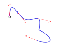
Curve direction.
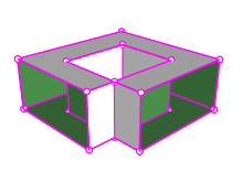
Surface normals are represented by arrows perpendicular to the surface, and the u‑ and v‑directions are indicated by arrows pointing along the surface. Closed surfaces always have the surface normals pointing to the exterior.
The Dir command can change the u‑, v‑, and normal‑directions of a surface. This direction can be important if you are applying textures to the surface.
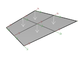
Surface direction.
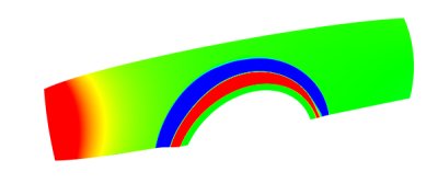
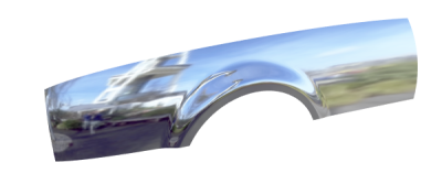
Visual surface analysis commands let you examine surfaces to determine smoothness. These commands use NURBS surface evaluation and rendering techniques to help you visually analyze surface smoothness with false color or reflection maps so you can see the curvature and breaks in the surface.
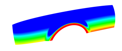
The CurvatureAnalysis command analyzes surface curvature using false color mapping. It analyzes Gaussian curvature, mean curvature, minimum radius of curvature, and maximum radius of curvature.
The EMap command displays a bitmap on the object so it looks like a scene is being reflected by a highly polished metal. This tool helps you find surface defects and validate your design intent.
The fluorescent tube environment map simulates tube lights shining on a reflective metal surface.
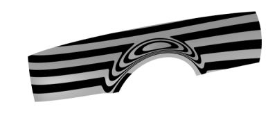
The Zebra command displays surfaces with reflected stripes. This is a way to visually check for surface defects and for tangency and curvature continuity conditions between surfaces.
The DraftAngleAnalysis command displays the draft angle relative to the construction plane that is active when you start the command.
The pull direction for the DraftAngleAnalysis command is the z‑axis of the construction plane. It also uses false color mapping.
Geometry problems such as Boolean or join failures can be caused by edges on surfaces that have become broken or edges between surfaces that have been moved through point editing so they create holes. An edge is a separate object that defines the surface’s boundary.
The ShowEdges command highlights naked edges, non-manifold edges or all edges of the surface.
|
|
|
|
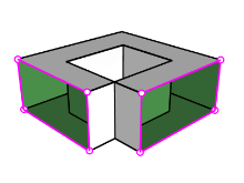
Naked edges
|
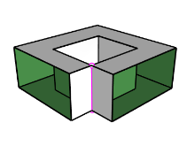
Non-manifold edges
|
All edges
|
The Properties command may tell you that a polysurface is open even though it looks closed. Some operations and export features require closed polysurfaces, and a model using closed polysurfaces is generally higher quality than one with small cracks and slivers.
When a surface is not joined to another surface, it has naked edges. Rhino provides a tool for finding the unjoined or “naked” edges. Use Properties command to examine the object details. A polysurface that has naked edges lists as an open polysurface. Use the ShowEdges command to display the unjoined edges.
Other edge tools let you split an edge, merge edges that meet end-to-end, or force surfaces with naked edges to join. You can rebuild edges based on internal tolerances. Other edge tools include:
Diagnostic tools report on an object’s internal data structure and select objects that may need repair. The output from the List, Check, SelBadObjects, and Audit3dmFile commands is normally most useful to a Rhino programmer to diagnose problems with surfaces that are causing errors.
Rhino for Windows © 2010-2018 Robert McNeel & Associates. 24-Nov-2021