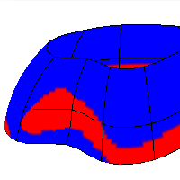
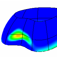
The DraftAngleAnalysis command visually evaluates surface draft-angle using false-color analysis.
Draft angle is used to design injection-molded parts that must eject from molds.
Steps
| 1. | Select objects. |
| 2. | In the Draft Angle dialog box, set the angle for the color display. The draft angle depends on the construction plane orientation. When the surface is vertical/perpendicular to the construction plane, the draft angle is zero. When the surface is parallel to the construction plane, the draft angle is 90 degrees. |
| 3. | Adjust the density of the mesh if the level of detail is not fine enough. |
Note
| ● | If you set the minimum and maximum angle to the same value, all portions of the surface that exceed the angle will be red.
|
| ● | The pull direction for DraftAngleAnalysis is the z-axis of the construction plane that is in the active viewport when the command starts. |
| ● | The normal direction of the surface is the same as the pull direction of the mold. You can check this with the Dir command. |
| ● | Changing the construction plane before using DraftAngleAnalysis lets you define any direction as the pull direction. |
The DraftAngleAnalysisOff command turns off draft angle analysis.
See also
Rhinoceros 5 © 2010-2015 Robert McNeel & Associates. 17-Sep-2015