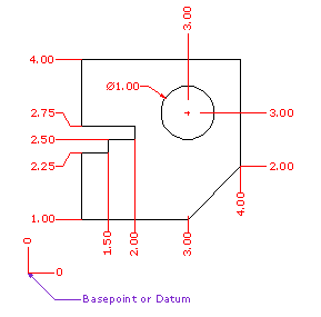
The DimOrdinate command dimensions the x- or y-distance from a base location.

Note
| ● | Ordinate dimensions show the horizontal or vertical distance from an origin point (called the basepoint) to a dimensioned feature, such as a hole Center or a feature in a part. |
| ● | Ordinate dimensions are widely used in CNC related manufacturing industries because the clutter caused by dimensions is minimized. |
| ● | This type of dimension prevents accumulated errors by showing the X or Y offset of the feature from the basepoint. |
Steps
| 1. | Pick a dimension point. An XDatum dimension is implied if your second pick is primarily above or below the first pick. A YDatum dimension is implied if your second pick is primarily left or right from the first pick. |
| 2. | Pick a leader endpoint. |
| 3. | Press Enter when finished placing dimensions. |
Note: The shape of the ordinate leader can be point edited after creation to avoid overlapping geometry.
Command-line options
Style
Enter the dimension style name.
XDatum
Overrides the implied biasing and forces an X-ordinate dimension.
YDatum
Overrides the implied biasing and forces a Y-ordinate dimension.
Basepoint
Changes the basepoint for the duration of the command. The basepoint reverts to the default construction plane origin when the DimOrdinate command is run again.
See also
Use text and dimensions for annotation
Manage angle brackets, dimension display, degree, diameter, plus/minus symbols.
Rhinoceros 5 © 2010-2015 Robert McNeel & Associates. 17-Sep-2015